-
== Introduction == <!--T:1-->
855 B (124 words) - 07:02, 11 January 2017
-
{| border="1"
| 60mm X 60mm X 1.6mm
3 KB (479 words) - 03:15, 11 September 2014
-
...0%" align="left"| *[[DS18B20 1 - Wire Digital Thermometer Module | DS18B20 1 - Wire Digital Thermometer Module (IM120710012)]]
! width="50%" align="left"| *[[ITDB02-1.8SP | ITDB02-1.8SP (IM120419001)]]
21 KB (2,507 words) - 08:11, 9 July 2018
-
{| border="1"
| 68.58mm X 58.42mm X 1.6mm
10 KB (1,672 words) - 09:38, 25 November 2015
-
*1. There is no USB connector on the board nor is there any USB hardware, you
{| border="1"
5 KB (760 words) - 07:56, 26 November 2015
-
{| border="1"
| 79.2mm X 53.8mm X 1.6mm
4 KB (680 words) - 06:21, 10 March 2017
-
{| border="1"
| 80.77mm X 57.66mm X 1.6mm
5 KB (736 words) - 03:47, 23 June 2016
-
{| border="1"
| 124.46mm X 72.39mm X 1.6mm
7 KB (1,171 words) - 03:47, 23 June 2016
-
{| border="1"
| 10mm X 82mm X 1.6mm
4 KB (528 words) - 03:44, 23 June 2016
-
{| border="1"
{| border="1"
4 KB (572 words) - 09:30, 9 December 2016
-
{| border="1"
2 KB (253 words) - 05:39, 11 June 2014
-
...owever, USB 4 is connected directly to the port and supports USB OTG. Pins 1 and 2 of the expansion header export the same USB OTG port.
.../2014/04/ibox-review-part-1-hardware/ by Michael Rodger <IBOX REVIEW (PART 1 – HARDWARE)>]
3 KB (458 words) - 06:52, 22 December 2016
-
The Android 3.1 platform (also backported to Android 2.3.4) introduces Android Open Accesso
* 4 Hardware serial ports (UART),1 Hardware TWI (I2C),1 Hardware SPI (up to 8Mbps)
7 KB (971 words) - 02:24, 24 November 2015
-
...ll Arduino compatible shields that work at 3.3V and are compliant with the 1.0 Arduino compatible pinout.
The Due follows the 1.0 pinout:
15 KB (2,521 words) - 10:16, 15 June 2014
-
{| border="1"
| 68.58mm X 58.42mm X 1.6mm
11 KB (1,795 words) - 10:16, 15 June 2014
-
{| border="1"
| 59mm X 77mm X 1.6mm
3 KB (501 words) - 02:23, 22 November 2014
-
{| border="1"
| 80.77mm X 57.66mm X 1.6mm
6 KB (980 words) - 04:00, 11 June 2014
-
{| border="1"
...lso with 2 KB used for the bootloader), the ATmega328 has 2 KB of SRAM and 1 KB of EEPROM.
7 KB (1,050 words) - 10:16, 15 June 2014
-
* Support for the Arduino IDE 1.0+ (Windows)
{| border="1"
4 KB (597 words) - 02:42, 28 June 2016
-
{| border="1"
| 78.74mm X 106.08mm X 1.6mm
3 KB (477 words) - 03:32, 11 August 2015
-
{| border="1"
| 68.6mm X58.5mm X 1.6mm
5 KB (736 words) - 10:16, 15 June 2014
-
{| border="1"
| 90.0mm X57.8mm X 1.6mm
6 KB (995 words) - 10:17, 15 June 2014
-
{| border="1"
| 131.0mm X 68.8mm X 1.6mm
7 KB (1,122 words) - 06:04, 17 June 2016
-
1. [[Download]] and install SDK in Debian
...GPIO pin number 1-26 with P1's first pin corresponding to GPIO pin number 1. Specially,
7 KB (1,108 words) - 07:44, 12 November 2014
-
a. Life support devices or systems are devices or systems which (1) are intended for surgical implant into the body, or (2) support or sustain
1 KB (212 words) - 06:36, 19 March 2015
-
{| border="1"
| PCB size||74.4mm X 50.3mm X 1.6mm
3 KB (419 words) - 06:11, 11 June 2014
-
{| border="1"
* 1*10/100M Ethernet
3 KB (456 words) - 05:57, 11 June 2014
-
'''1. What is ITEAD SDK?'''
...GPIO pin number 1-26 with P1's first pin corresponding to GPIO pin number 1. Specially,
7 KB (1,085 words) - 09:10, 14 August 2014
-
{| border="1"
| PCB size||83.8mm X 68.6mm X 1.6mm
3 KB (373 words) - 03:07, 21 July 2015
-
...d, including a large prototyping space of both connected and unconnected 0.1-inch spaced through-holes.
{| border="1"
708 B (92 words) - 10:17, 15 June 2014
-
| Specific Gravity||—||1.91-1.2
*'''1. We offer several download links here in case one of them doesn't work for
7 KB (1,045 words) - 03:04, 11 April 2016
-
{| border="1"
| PCB size||109.3mm X 76.2mm X 1.6mm
5 KB (701 words) - 10:16, 15 June 2014
-
{| border="1"
| PCB size||82.8mm X 56.6mm X 1.6mm
2 KB (317 words) - 06:12, 11 June 2014
-
{| border="1"
| DM0||IO1||1||2||IO2||DP0
3 KB (410 words) - 10:15, 28 October 2014
-
{| border="1"
| PCB size ||53.3mm X 68.6mm X 1.6mm
3 KB (504 words) - 06:00, 11 June 2014
-
{| border="1"
| PCB size ||53.3mm X 68.6mm X 1.6mm
3 KB (481 words) - 06:17, 11 June 2014
-
...able resistors to calibrate the current error is a good idea, because just 1 lap the resistor change from 0R to1K , you cannot get the exact value you n
{| border="1"
5 KB (741 words) - 10:13, 7 August 2014
-
1. Set up the physical configuration
8. In the "Direct" mode enter 'at' commands - start with "at+ascii=1".
5 KB (790 words) - 09:48, 21 May 2014
-
{| border="1"
| PCB size||55.8mm X 68.8mm X 1.6mm
5 KB (803 words) - 02:16, 26 July 2014
-
...ar XBee module. This unit works with all XBee modules including the Series 1 and Series 2 (and 2.5), standard and Pro version.
(1)RSSI: Receiver Signal Strength Indication
4 KB (511 words) - 06:03, 11 June 2014
-
{| border="1"
| PCB size||80.36mm X 56.12mm X 1.6mm
5 KB (759 words) - 07:48, 9 May 2016
-
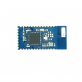
BT [[Shield]] V2.1 is a Serial port Bluetooth module (Slave) breakout board, and it’s compat
{| border="1"
4 KB (506 words) - 06:04, 11 June 2014
-
{| border="1"
| PCB size||53.3mm X 47mm X 1.6mm
18 KB (2,553 words) - 06:07, 11 June 2014
-
* Class 1 (1W@1800/1900MHz)
{| border="1"
7 KB (1,134 words) - 03:11, 13 May 2016
-
..., including: a large prototyping space of both connected and unconnected 0.1" spaced through-holes, a reset button, LED for D13 pin indicating.
{| border="1"
1 KB (149 words) - 06:09, 11 June 2014
-
...likewise, horizontal movement of the joystick can be tracked on analog pin 1.
{| border="1"
3 KB (513 words) - 06:40, 21 November 2014
-
| PCB size||68.33mm X 60.7mm X 1.6mm
Figure 1 Top Map
4 KB (580 words) - 08:33, 23 May 2017
-
[[File:Arduino GPS shield 1.jpg|thumb|400px|right]]
{| border="1"
5 KB (690 words) - 10:10, 13 April 2016
-
{| border="1"
| PCB size||56mm X 54mm X 1.6mm
3 KB (413 words) - 06:13, 11 June 2014
-
{| border="1"
| PCB size||67.3mm X 59.1mm X 1.6mm
5 KB (726 words) - 06:16, 11 June 2014
 Notice
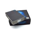


.jpg)