Difference between revisions of "ITEAD 3G Shield"
(→Hardware) |
(→Installation) |
||
| Line 100: | Line 100: | ||
==Installation== | ==Installation== | ||
| + | (1) UART Multiplexer | ||
| + | |||
| + | The UART multiplexer can assign Tx / Rx of SIM5216E to D0 ~D7. | ||
| + | |||
| + | ''Note: Don’t assign TX/RX of SIM5216E to the same digital pin at the same time.'' | ||
| + | |||
| + | (2)Operation Level Setting Switch | ||
| + | |||
| + | When install 3G [[shield]] to Arduino, please check the operation | ||
| + | voltage level of development board. If the voltage is 3.3V (Leaf | ||
| + | maple), set the Operation Level Setting switch to 3.3V. If the | ||
| + | voltage is 5V (Arduino), set the Operation Level Setting switch to | ||
| + | 5V. | ||
| + | |||
| + | (3) Indicator Description | ||
| + | |||
| + | * PWR: When the board is connected to the power, the power | ||
| + | indicator light is on. | ||
| + | * 2.8V: The 2.8 V power is properly if the indicator light is on. | ||
| + | * 3.3V:The 3.3 V power is properly if the indicator light is on. | ||
| + | * Status:The indicator light has four statuses. As shown below: | ||
| + | |||
| + | {| class="wikitable" | ||
| + | |- | ||
| + | | align="center" style="background:#f0f0f0;"|'''LED Status''' | ||
| + | | align="center" style="background:#f0f0f0;"|'''Module Status''' | ||
| + | |- | ||
| + | | Always On ||Searching Network/Call Connect | ||
| + | |- | ||
| + | | 200ms ON, 200ms OFF ||Data Transmit | ||
| + | |- | ||
| + | | 800ms ON, 800ms OFF ||Registered network | ||
| + | |- | ||
| + | | Off||Power off / Sleep | ||
| + | |} | ||
==Download== | ==Download== | ||
==Useful Links== | ==Useful Links== | ||
Revision as of 07:18, 26 May 2014
Contents
Overview
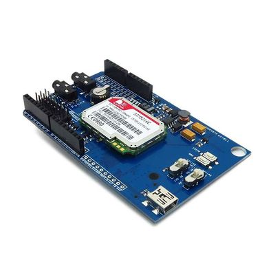
The 3G shield is based on SIM5216A or SIM5216E module. The 3G shield can be used for 3G communication, it is controlled via AT commands and fully compatible with Arduino. The difference between SIM5216A and SIM5216E is as folllows:

Features
- Multi-modules support: SIM5216A/SIM5216E/SIM5216J
- Configurable pins for UART communication
- With the MIC and earphone interface
- Control via AT commands
- RTC supported with Super Capacitor
- Optimization of the power supply circuit
- Operation temperature: -40℃ ~ +85℃
Specifications
| PCB size | 91.93mmX57.15mm X 1.6mm |
| Indicators | PWR,5V,2.8V, Status |
| Power supply | 5V support by Arduino |
| Communication Protocol | UART |
Electrical Characteristics
| Specification | Min | Type | Max | Unit |
| Power Voltage | 4.5 | 5 | 5.5 | VDC |
| Input Voltage VH (5V): | 2.3 | 5 | 5.5 | V |
| Input Voltage VL (5V): | -0.3 | 0 | 1 | V |
| Current Consumption | - | - | 300 | mA |
Hardware

Figure 1 Top Map
Pin Map
| Arduino PIN | Description |
| D0 | - |
| D1 | - |
| D2 | - |
| D3 | - |
| D4 | - |
| D5 | - |
| D6 | - |
| D7 | - |
| D8 | POWER (High Active) |
| D9 | Reset (High Active) |
| D10 | - |
| D11 | - |
| D12 | - |
| D13 | - |
| A0 | - |
| A1 | - |
| A2 | - |
| A3 | - |
| A4 | - |
| A5 | - |
Installation
(1) UART Multiplexer
The UART multiplexer can assign Tx / Rx of SIM5216E to D0 ~D7.
Note: Don’t assign TX/RX of SIM5216E to the same digital pin at the same time.
(2)Operation Level Setting Switch
When install 3G shield to Arduino, please check the operation voltage level of development board. If the voltage is 3.3V (Leaf maple), set the Operation Level Setting switch to 3.3V. If the voltage is 5V (Arduino), set the Operation Level Setting switch to 5V.
(3) Indicator Description
- PWR: When the board is connected to the power, the power
indicator light is on.
- 2.8V: The 2.8 V power is properly if the indicator light is on.
- 3.3V:The 3.3 V power is properly if the indicator light is on.
- Status:The indicator light has four statuses. As shown below:
| LED Status | Module Status |
| Always On | Searching Network/Call Connect |
| 200ms ON, 200ms OFF | Data Transmit |
| 800ms ON, 800ms OFF | Registered network |
| Off | Power off / Sleep |
 Notice