|
|
| Line 1: |
Line 1: |
| − | <languages/>
| + | {| class="FCK__ShowTableBorders" align="left" |
| − | | + | |
| − | <translate>
| + | |
| − | ==Overview== <!--T:1-->
| + | |
| − | [[File:IM140714004_3.jpg|thumb|400px|right]]
| + | |
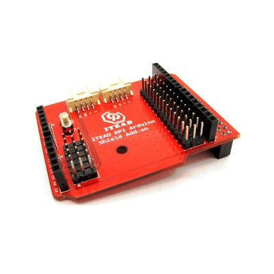
| − | Compared to Arduino, it's hard to find the shields and electronic brick customized for Raspberry Pi. This Arduino [[Shield]] Add-on has extended RPI 32PIN Connector to Arduino PIN, which will facilitate connections to all kinds of arduino shields. Meanwhile, two groups of electronic brick interfaces are equipped on the add-on, which are free to be connected to various electronic bricks.
| + | |
| − | | + | |
| − | <!--T:2-->
| + | |
| − | We do not only offer this convenient add-on for Raspberry Pi, but also provide an SDK that help you transplant divers of Arduino into Raspberry Pi. After installing the SDK, you can drive this add-on as easily as you do on Arduino.
| + | |
| − | | + | |
| − | Go shopping [http://imall.iteadstudio.com/im140714004.html Raspberry Pi Arduino Shield ADD-ON (SKU: IM140714004)]
| + | |
| − | | + | |
| − | ==Features== <!--T:3-->
| + | |
| − | *extend RPI 32pin connector to Arduino [[Shield]]
| + | |
| − | *two groups of Grove electronic brick interfaces
| + | |
| − | *two electronic brick intefaces
| + | |
| − | *two optional voltage levels 3V3/5V
| + | |
| − | | + | |
| − | ==Specification== <!--T:4-->
| + | |
| − | {| border="1" | + | |
| − | | PCB Size||62.33X49.67X1.6mm
| + | |
| | |- | | |- |
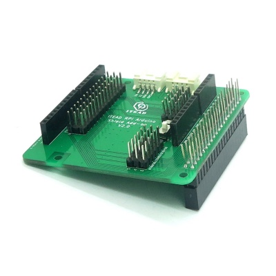
| − | | Interface||IIC, UART, Arduino [[Shield]] | + | | [[File:IM150627002 (7).jpg|400px|Rasspberry Pi Arduino Sheild Add-on V2.0]] <br> |
| | + | | [[File:IM140714004_3.jpg|400px|Rasspberry Pi Arduino Sheild Add-on V1.0]]<br> |
| | |- | | |- |
| | + | | <div style="text-align: center">[[RPI Arduino Sheild Add-on V2.0|RPI Arduino Sheild Add-on V2.0(SKU: IM150627002)]]</div> |
| | + | | <div style="text-align: center">[[RPI Arduino Sheild Add-on V1.0|RPI Arduino Sheild Add-on V1.0(SKU: IM140714004)]]</div> |
| | |} | | |} |
| | + | <br clear="all"> |
| | | | |
| − | ==Electrical Characteristics== <!--T:5--> | + | ==V2.0 Change List== |
| − | {| class="wikitable"
| + | *It has extended RPI Connector to Arduino PIN |
| − | | align="center" style="background:#f0f0f0;"|'''Characteristics'''
| + | *It is equipped with two groups of electronic brick interfaces |
| − | | align="center" style="background:#f0f0f0;"|'''Symbol'''
| + | |
| − | | align="center" style="background:#f0f0f0;"|'''Min'''
| + | |
| − | | align="center" style="background:#f0f0f0;"|'''Typ'''
| + | |
| − | | align="center" style="background:#f0f0f0;"|'''Max'''
| + | |
| − | | align="center" style="background:#f0f0f0;"|'''Unit'''
| + | |
| − | |-
| + | |
| − | | Power supply voltage||VDD||3||3.3||3.5||V
| + | |
| − | |-
| + | |
| − | |}
| + | |
| − | | + | |
| − | ==Hardware== <!--T:6--> | + | |
| − | | + | |
| − | <!--T:7-->
| + | |
| − | [[File:IM140714004pic1.jpg|500px]]
| + | |
| − | [[File:IM140714004pic2.jpg|500px]]
| + | |
| − | [[File:IM140714004pic3.jpg|500px]]
| + | |
| − | | + | |
| − | ==Pin Map== <!--T:8-->
| + | |
| − | {| class="wikitable"
| + | |
| − | | align="center" style="background:#f0f0f0;"|'''Pin Index'''
| + | |
| − | | align="center" style="background:#f0f0f0;"|'''Pin Name'''
| + | |
| − | | align="center" style="background:#f0f0f0;"|'''Arduino [[Shield]]'''
| + | |
| − | | align="center" style="background:#f0f0f0;"|'''Description'''
| + | |
| − | |-
| + | |
| − | | 1||3V3||-||
| + | |
| − | |-
| + | |
| − | | 2||5V||-||
| + | |
| − | |-
| + | |
| − | | 3||SDA||A4|| SDA
| + | |
| − | |-
| + | |
| − | | 4||5V||-||
| + | |
| − | |-
| + | |
| − | | 5||SCL||A5|| SCL
| + | |
| − | |-
| + | |
| − | | 6||GND||-||
| + | |
| − | |-
| + | |
| − | | 7||GPIO7||D9||
| + | |
| − | |-
| + | |
| − | | 8||TXD||D1|| UART TXD
| + | |
| − | |-
| + | |
| − | | 9||GND||-||
| + | |
| − | |-
| + | |
| − | | 10||RXD||D0||UART RXD
| + | |
| − | |-
| + | |
| − | | 11||GPIO0||D2||
| + | |
| − | |-
| + | |
| − | | 12||GPIO1||D3||
| + | |
| − | |-
| + | |
| − | | 13||GPIO2||D4||
| + | |
| − | |-
| + | |
| − | | 14||GND||-||
| + | |
| − | |-
| + | |
| − | | 15||GPIO3||D5||
| + | |
| − | |-
| + | |
| − | | 16||GPIO4||D6||
| + | |
| − | |-
| + | |
| − | | 17||3V3||-||
| + | |
| − | |-
| + | |
| − | | 18||GPIO5||D7||
| + | |
| − | |-
| + | |
| − | | 19||MOSI||D11||
| + | |
| − | |-
| + | |
| − | | 20||GND||-||
| + | |
| − | |-
| + | |
| − | | 21||MISO||D12||
| + | |
| − | |-
| + | |
| − | | 22||GPIO6||D8||
| + | |
| − | |-
| + | |
| − | | 23||SCK||D13||
| + | |
| − | |-
| + | |
| − | | 24||CE0||D10||
| + | |
| − | |-
| + | |
| − | | 25||GND||-||
| + | |
| − | |-
| + | |
| − | | 26||CE1||A3||
| + | |
| − | |-
| + | |
| − | |}
| + | |
| − | | + | |
| − | ==Instruction== <!--T:9-->
| + | |
| − | *Plug Rpi Arduino [[Shield]] Add-on into RPI V2, connect SHT10 to IIC interface through 4-pin wires. Power Raspberry Pi V2. | + | |
| − | *[[Download]] the SDK from this link: https://github.com/itead/Segnix and then install it. | + | |
| − | *Modify the file ReadSHT1xValues.ino
| + | |
| − | : modified codes as below:
| + | |
| − | ::define dataPin 3
| + | |
| − | ::define clockPin 5
| + | |
| − | *Enter into the directory '''libraries/itead_SHT1x/examples/ReadSHT1xValues''', compile and run the file '''ReadSHT1xValues.ino'''
| + | |
| − | :Command as below to compile ReadSHT1xValues.ino
| + | |
| − | ::$ iteadcompile ReadSHT1xValues ReadSHT1xValues.ino
| + | |
| − | :Command to run this program
| + | |
| − | ::$ sudo ./ ReadSHT1xValues
| + | |
| − | *When the compilation is done, you can read the temperature and humidity data from the terminal.
| + | |
| − | | + | |
| − | <!--T:10-->
| + | |
| − | [[File:IM140714004in1.jpg|400px]]
| + | |
| − | [[File:IM140714004in2.jpg|500px]]
| + | |
| − | | + | |
| − | ==Download== <!--T:11-->
| + | |
| − | Schematic---[[File:SHC_IM140714004.pdf]]
| + | |
| − | | + | |
| − | ==Useful Link== <!--T:12-->
| + | |
| − | https://github.com/itead/Segnix
| + | |
| − | | + | |
| − | </translate>
| + | |


 Notice