Difference between revisions of "Core EVB"
m (→Overview) |
m (→Download) |
||
| Line 262: | Line 262: | ||
*Shematic—[[:File:IM140725003 - Core EVB - schematic.pdf]] | *Shematic—[[:File:IM140725003 - Core EVB - schematic.pdf]] | ||
*Design files - https://github.com/itead/ITEADHW-Core-EVB | *Design files - https://github.com/itead/ITEADHW-Core-EVB | ||
| + | *[http://www.te.com/commerce/DocumentDelivery/DDEController?Action=srchrtrv&DocNm=2013310&DocType=Customer+Drawing&DocLang=English The Clip-clasp datasheet] | ||
==Related Products== | ==Related Products== | ||
Revision as of 07:24, 23 October 2014
Contents
Overview
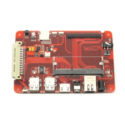
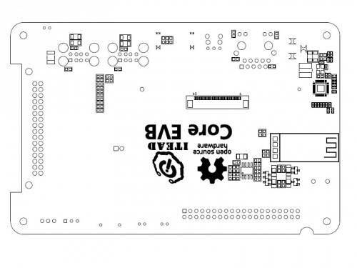
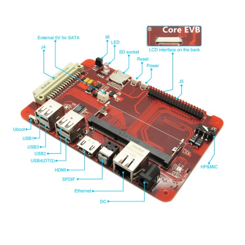
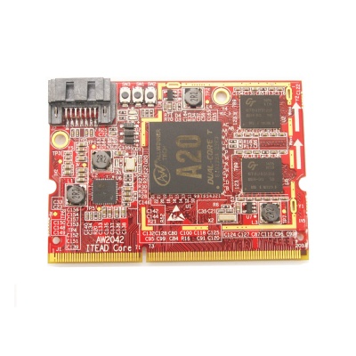
Core EVB is a customized evaluation board for ITEAD Core AW204x, which pinouts the functional pins of AW204x to the corresponding physical interface such as USB ports, SD card slot Ethernet port etc. Moreover, Core EVB provides a 40 pins interface that is compatible with RPI B+, which will help developers utilize the existing Add-on more easily.
Common A20 development boards in the market only provide Line-in/Line-out interface so that they can't drive a loudspeaker directly. However, we add power amplifier so that it can drive 4ohm or 8ohm speaker easily.
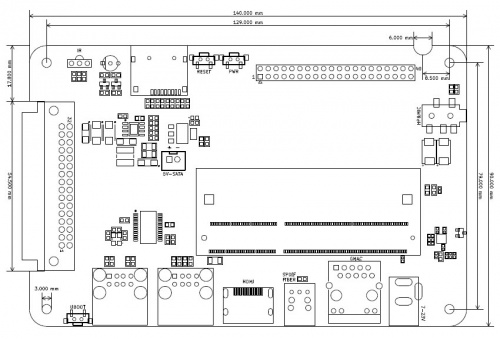
The dimension of Core EVB is designed according to an aluminum box, thus, this development board can be installed to IBOX.
Go shopping Core EVB(IM140725003)
Specification
| Compatible Module | AW2041 & AW2042 | |
| Display | LVDS * 1 | 18/24 bit single or dual channel |
| HDMI * 1 | HDMI 1.4 | |
| Audio | audio jack * 1 | 3.5mm CTIA,drive capability: 8ohm speaker @3w |
| SPDIF * 1 | SPDIF fiber | |
| I/O | 2*16 pin (J4) | UART/I2C/SPI/I2S/GPIO |
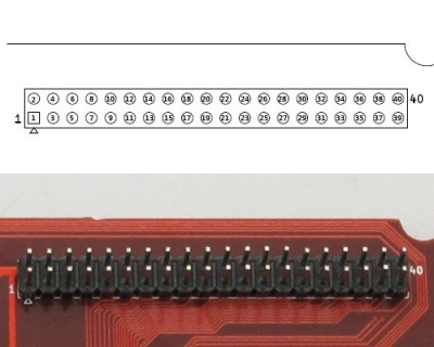
| 2*20 pin (J5) | UART/I2C/SPI/GPIO, Compatible with RPI B+ 40-pin interface | |
| Ethernet | Ethernet * 1 | 10M/100M/1000M adaptable |
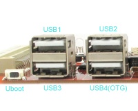
| USB | 4 | 3 for USB2.0 full speed, 1 for USB OTG |
| IR | 1 | |
| Indicator | 1 | bicolor LED |
| Button | 3 | Power/Reset/FEL |
| Power | 1 | 7-23V DC in,2.5mm power jack |
| Storage | SATA * 1 | on-board SATA on AW204x;on-board external 5V SATA on Core EVB |
| Micro-SD * 1 | support micro SD card up to 32G | |
Electronic Characteristics
Working environment
- Temperature: 0℃ ~ 60℃
- Humidity:5% ~ 95%
Storage environment:
- Temperature: -40℃ ~ 80℃
- Humidity: 5% ~ 95%
Current Consumption
The current consumption is based on the following situation without any device assessing to Core EVB
- Core: AW2041
- Core EVB
| Min | Type | Max | Unit | |
| Current Consumption | - | 200 | 300 | mA |
Hardware
- Dimension: 140.2mm×90mm
- Wight:82g
Pin Map
- USB
| Number | Name |
| 1 | +5V |
| 2 | USB_Data- |
| 3 | USB_Data+ |
| 4 | GND |
- J4(32-pin) interface
| name | IO | number | number | IO | name |
| DM0 | 1 | 2 | DP0 | ||
| VGA-R | TVOUT2 | 3 | 4 | NC | |
| VGA-G | TVOUT0 | 5 | 6 | TVOUT1 | VGA-B |
| VGA-HS | PD26 | 7 | 8 | PD27 | VGA-VS |
| UART0-TX | PB22 | 9 | 10 | PB23 | UART0-RX |
| UART1-TX | PG10 | 11 | 12 | PG11 | UART1-RX |
| I2C1-SDA | PB19 | 13 | 14 | PB18 | I2C1-SCL |
| SPIO-SCK | PI11 | 15 | 16 | PI13 | SPIO-MI |
| SPI0-MO | PI12 | 17 | 18 | PI10 | SPI0-CS |
| LINL | 19 | 20 | HPL | ||
| LINR | 21 | 22 | HPR | ||
| HCOM | 23 | 24 | UBOOT | ||
| I2S-MCLK | PB5 | 25 | 26 | PB6 | I2S-BCLK |
| I2S-LRCLK | PB7 | 27 | 28 | PB8 | I2S-DOUT |
| GND | 29 | 30 | 3V3 | ||
| 5V | 31 | 32 | VIN |
- J5 (40pin RPI B+)
| name | IO | number | number | IO | name |
| 3V3 | 1 | 2 | 5V | ||
| I2C1-SDA | PB19 | 3 | 4 | 5V | |
| I2C1-SCL | PB18 | 5 | 6 | GND | |
| PI15 | 7 | 8 | PG10 | UART1-TX | |
| GND | 9 | 10 | PG11 | UART1-RX | |
| PI16 | 11 | 12 | PI17 | ||
| PI18 | 13 | 14 | GND | ||
| PI19 | 15 | 16 | PI20 | ||
| 3V3 | 17 | 18 | PI21 | ||
| SPI0-MO | PI12 | 19 | 20 | GND | |
| SPI0-MI | PI13 | 21 | 22 | PG0 | |
| SPI0-SCK | PI11 | 23 | 24 | PI10 | SPI0-CS |
| GND | 25 | 26 | PI14 | SPI0-CS1 | |
| I2C2-SDA | PB21 | 27 | 28 | PB20 | I2C2-SCL |
| PG1 | 29 | 30 | GND | ||
| PG2 | 31 | 32 | PG3 | ||
| PG4 | 33 | 34 | GND | ||
| PG5 | 35 | 36 | PG6 | ||
| PG7 | 37 | 38 | PG8 | ||
| GND | 39 | 40 | PG9 |
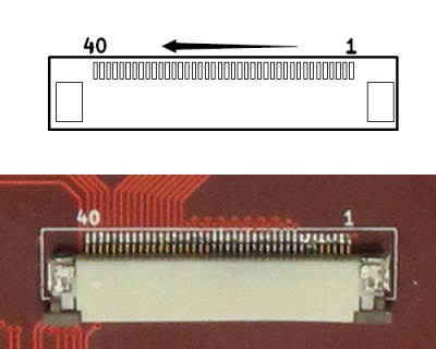
- LCD pin map
| name | IO | number | number | IO | name |
| GND | 1 | 2 | GND | ||
| GND | 3 | 4 | GND | ||
| GND | 5 | 6 | GND | ||
| GND | 7 | 8 | GND | ||
| PD27 | PD27 | 9 | 10 | PD26 | PD26 |
| PD25 | PD25 | 11 | 12 | PD24 | PD24 |
| PD23 | PD23 | 13 | 14 | PD22 | PD22 |
| PD21 | PD21 | 15 | 16 | PD20 | PD20 |
| PD19 | PD19 | 17 | 18 | PD18 | PD18 |
| PD17 | PD17 | 19 | 20 | PD16 | PD16 |
| PD15 | PD15 | 21 | 22 | PD14 | PD14 |
| PD13 | PD13 | 23 | 24 | PD12 | PD12 |
| PD11 | PD11 | 25 | 26 | PD10 | PD10 |
| PD9 | PD9 | 27 | 28 | PD8 | PD8 |
| PD7 | PD7 | 29 | 30 | PD6 | PD6 |
| PD5 | PD5 | 31 | 32 | PD4 | PD4 |
| PD3 | PD3 | 33 | 34 | PD2 | PD2 |
| PD1 | PD1 | 35 | 36 | PD0 | PD0 |
| Y2 | 37 | 38 | Y1 | ||
| X2 | 39 | 40 | X1 |
Core Installation
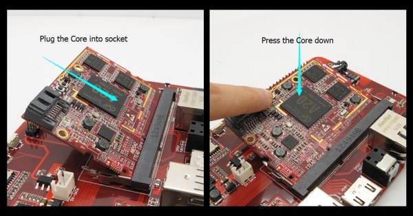
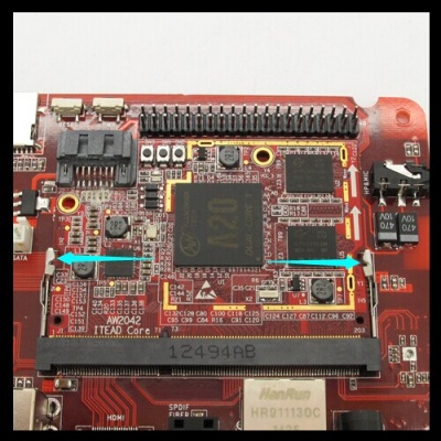
Brand new SO-DIMM 204 pins socket is for plugging in and pulling out ITEAD core easily. The following picture will show you how to install core to EVB.
You can unplug the core by pulling out the clasps both on the right and left side.
Download
- Shematic—File:IM140725003 - Core EVB - schematic.pdf
- Design files - https://github.com/itead/ITEADHW-Core-EVB
- The Clip-clasp datasheet
 Notice