Difference between revisions of "IoTgo Shield"
From ITEAD Wiki
m (→Overview) |
m (→Download) |
||
| Line 80: | Line 80: | ||
==Download== | ==Download== | ||
| + | [[:File:IM141125003 - IoTgo Shield - schematic.pdf]] | ||
Revision as of 07:42, 10 January 2015
Contents
Overview
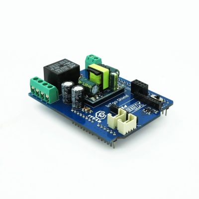
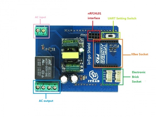
With an on-board AC-DC module, Arduino IoTgo shield can transfer AC 110~250V to DC 5V, so it can be the power supply to arduino. Meanwhile, mainboards can control some home applications by setting the relays on this shield. Moreover, IoTgo shield has an Xbee interface and a Nrf24l01 interface. By using this shield, you can make some remote control home application projects with no effort.
Specifications
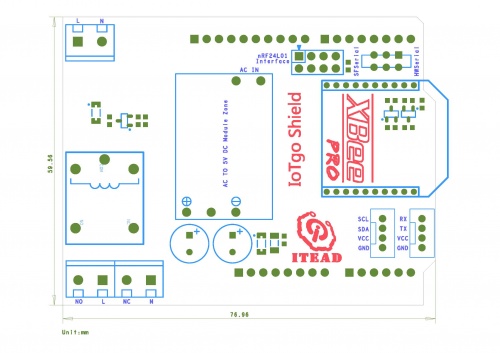
| PCB size | 76.96mm X 59.56mm X 1.6mm |
| Power supply | AC 85~265V 50/60Hz |
| Power output | DC5V |
Electrical Characteristics
| Min | Type | Max | Unit | |
| Power Voltage | 85 | 220 | 265 | AVCC |
| AC-DC 5V Output average current | 0 | - | 700 | mA |
| Max load current(relay) | 3 | A | ||
| Ripple wave voltage(Vpp) | 80 | 150 | 200 | mV |
Hardware
Pinmap
- Nrf24L01 Socket
| Index of Interface | Name of Interface | Index of Arduino |
| 1 | GND | - |
| 2 | 3V3 | |
| 3 | CE | D8 |
| 4 | CS | D9 |
| 5 | SCK | D13 |
| 6 | MOSI | D11 |
| 7 | MISO | D12 |
| 8 | IRQ | - |
- AC socket
| Index of Interface | Name of Interface | Description |
| 1 | N | Zero line |
| 2 | L | Live line |
| 3 | NO | Shorted to L while relay is activated |
| 4 | NC | Shorted to L while relay is not activated |
 Notice

