Difference between revisions of "MicroECG"
(Created page with "==Overview== right MicroECG is an ECG monitoring module based on nRF51822 BLE chip and BL1860 ECG chip, which can transport heart informa...") |
m (→Overview) |
||
| (12 intermediate revisions by the same user not shown) | |||
| Line 8: | Line 8: | ||
This ECG module is easy to use. Data can be transported through either UART or BLE. When the switch on the board is set to the BLE side, data can be transported through BLE. In this case, one can use app on one’s phone to receive the heart rate from this module. When the switch on the board is set to the UART side, data can be transported through UART. In this case, one can control the board with some AT commands. | This ECG module is easy to use. Data can be transported through either UART or BLE. When the switch on the board is set to the BLE side, data can be transported through BLE. In this case, one can use app on one’s phone to receive the heart rate from this module. When the switch on the board is set to the UART side, data can be transported through UART. In this case, one can control the board with some AT commands. | ||
| − | Go shopping [https://www.itead.cc/microecg.html MicroECG (SKU:IM161018001)] | + | Go shopping [https://www.itead.cc/microecg.html MicroECG (SKU:IM161018001) (Coming Soon!)] |
==Specification== | ==Specification== | ||
| Line 25: | Line 25: | ||
! scope="col" | Parameter || scope="col" | Min || scope="col" | Typical || scope="col" | Max || scope="col" | Unit | ! scope="col" | Parameter || scope="col" | Min || scope="col" | Typical || scope="col" | Max || scope="col" | Unit | ||
|- | |- | ||
| − | | Input Volt | + | | Input Volt || style="text-align:right" | 3 || style="text-align:right" | 3.3 || style="text-align:right" | 3.6 || VDC |
|- | |- | ||
| − | + | | Input voltage VinH || style="text-align:right" |3 || style="text-align:right" | 3.3 || style="text-align:right" | 3.6 || V | |
| − | + | ||
| − | | Input voltage VinH || style="text-align:right" | 3 || style="text-align:right" | 3.3 || style="text-align:right" | 3.6 || V | + | |
|- | |- | ||
| Input voltage VinL || style="text-align:right" | -0.3 || style="text-align:right" | 0 || style="text-align:right" | 0.5 || V | | Input voltage VinL || style="text-align:right" | -0.3 || style="text-align:right" | 0 || style="text-align:right" | 0.5 || V | ||
| − | |||
| − | |||
|- | |- | ||
| Baud rate || style="text-align:right" | || style="text-align:right" | 9600 || style="text-align:right" | || bps | | Baud rate || style="text-align:right" | || style="text-align:right" | 9600 || style="text-align:right" | || bps | ||
|} | |} | ||
| + | |||
==Hardware== | ==Hardware== | ||
| − | [[File: | + | [[File:MicroECG-Hardware-1.jpg|400px]] |
| + | |||
| + | [[File:MicroECG-Hardware-2.jpg|400px]] | ||
{| class="wikitable" | {| class="wikitable" | ||
| Line 45: | Line 44: | ||
| No. || Pin Name | | No. || Pin Name | ||
|- | |- | ||
| − | | 1 || | + | | 1 || 3V3 |
|- | |- | ||
| − | | 2 || | + | | 2 || SWDCLK |
|- | |- | ||
| − | | 3 || | + | | 3 || SWDIO/RST |
|- | |- | ||
| − | | 4 || | + | | 4 || TXD(P0.12) |
| − | + | ||
| − | + | ||
| − | + | ||
|- | |- | ||
| − | | | + | | 5 || RXD(P0.11) |
|- | |- | ||
| − | | | + | | 6 || GND |
|- | |- | ||
| − | | | + | | 7 || GND |
|- | |- | ||
| − | | | + | | 8 || LA |
|- | |- | ||
| − | | | + | | 9 || RA |
|- | |- | ||
| − | | | + | | 10 || RLD |
|- | |- | ||
| − | | 11 || | + | | 11 || NC |
| − | + | ||
| − | + | ||
| − | + | ||
|- | |- | ||
| − | | | + | | 12 || NC |
| − | + | ||
| − | + | ||
| − | + | ||
| − | + | ||
| − | + | ||
| − | + | ||
| − | + | ||
| − | + | ||
| − | + | ||
| − | + | ||
| − | + | ||
| − | + | ||
|} | |} | ||
==Interface Functions== | ==Interface Functions== | ||
| − | * | + | *SWDCLK: SWD interface clock line |
| − | * | + | *SWDIO/RST: SWD interface data line |
| − | * | + | *RXD/TXD: serial, support AT command |
| − | * | + | *LA: left arm signal input pin |
| − | * | + | *RA: right arm signal input pin |
| − | * | + | *RLD: right arm drive feedback output pin |
| − | + | 1.Power up this module with 3.3V. And use ECG Limb Clamp (IM161025001) and ECG Lead Wire (IM161025002) to clamp your arm. | |
| − | + | ||
| − | 1. | + | |
| − | 2. | + | 2.Run the BLE app on the phone. Click and turn into the “HRM” mode and then connect to the “ITEAD_BL18_ECG” device. |
| − | 3. | + | 3.Just wait a while and the heart rate will be displayed. |
| − | + | [[File:heart_rate_dectect.jpg|400px]] | |
| − | |||
| − | + | AT commands: | |
| − | + | ||
| − | |||
| − | |||
| − | |||
| − | |||
| − | |||
| − | |||
| − | |||
1.“AT\r” | 1.“AT\r” | ||
| Line 127: | Line 97: | ||
2.“ATdataTypeR\r” | 2.“ATdataTypeR\r” | ||
| − | This command is a string and used to set the data type to row data. | + | This command is a string and used to set the data type to row data. |
| − | + | ||
When the command runs successfully , "Type:R\nOK\r\n" will be returned. | When the command runs successfully , "Type:R\nOK\r\n" will be returned. | ||
| Line 136: | Line 106: | ||
This command is a string and used to set the data type to heart rate. | This command is a string and used to set the data type to heart rate. | ||
| − | + | ||
When this command runs successfully, "Type:H\nOK\r\n" will be returned. | When this command runs successfully, "Type:H\nOK\r\n" will be returned. | ||
| − | + | ||
This command can not run successfully when the “ATstartRead\r” is running. | This command can not run successfully when the “ATstartRead\r” is running. | ||
4.“ATdataType?\r” | 4.“ATdataType?\r” | ||
| − | |||
This command is a string and used to get the current data type. | This command is a string and used to get the current data type. | ||
| Line 165: | Line 134: | ||
When the hardware connection of ECG cable is not ok, “ERROR\r\n” wiil be returned. | When the hardware connection of ECG cable is not ok, “ERROR\r\n” wiil be returned. | ||
| − | When the hardware is ok, “OK\r\n” will be returned firstly, and then the data will be transported continuously as soon as the data itself is updated | + | When the hardware is ok, “OK\r\n” will be returned firstly, and then the data will be transported continuously as soon as the data itself is updated. |
7.“ATstopRead\r” | 7.“ATstopRead\r” | ||
| Line 174: | Line 143: | ||
==Useful Link== | ==Useful Link== | ||
| + | [[:File:IM161018001-MicroECG-PCBVIEW.pdf]] | ||
| + | |||
| + | [[:File:IM161018001-MicroECG-schematic.pdf]] | ||
| + | |||
| + | [[:File:IM161018001-MicroECG-dimension.pdf]] | ||
| + | |||
| + | [[:File:nRF51822_PS_v3.1.pdf]] | ||
[http://dl.itead.cc/BL18_ECG_Maven/nRFToolbox.apk nRFToolbox.apk] | [http://dl.itead.cc/BL18_ECG_Maven/nRFToolbox.apk nRFToolbox.apk] | ||
| + | |||
| + | [https://www.itead.cc/ecg-limb-clamp.html ECG Limb Clamp] | ||
| + | |||
| + | [https://www.itead.cc/ecg-lead-wire.html ECG Lead Wire] | ||
Latest revision as of 09:30, 21 February 2017
Contents
Overview
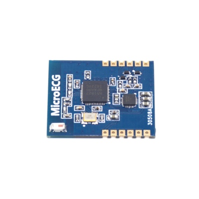
MicroECG is an ECG monitoring module based on nRF51822 BLE chip and BL1860 ECG chip, which can transport heart information through either UART or BLE. Users can control nRF51822 via AT Commands. Also, they can use the open-source software to develop their own firmware, making it to support more functions.
The heart information includes row data and the heart rate. The row data is the result of ADC detection, representing the strength of heart beat. The row data can be used to draw ECG directly. And the heart rate is the result of calculation with the row data.
This ECG module is easy to use. Data can be transported through either UART or BLE. When the switch on the board is set to the BLE side, data can be transported through BLE. In this case, one can use app on one’s phone to receive the heart rate from this module. When the switch on the board is set to the UART side, data can be transported through UART. In this case, one can control the board with some AT commands.
Go shopping MicroECG (SKU:IM161018001) (Coming Soon!)
Specification
| PCB Size | 22mm X 26mm X 1.6mm |
|---|---|
| Input Voltage (vcc) | 3.3V |
| Microprocessor | nRF51822 |
| Interface | UART, BLE |
Electrical Characteristics
| Parameter | Min | Typical | Max | Unit |
|---|---|---|---|---|
| Input Volt | 3 | 3.3 | 3.6 | VDC |
| Input voltage VinH | 3 | 3.3 | 3.6 | V |
| Input voltage VinL | -0.3 | 0 | 0.5 | V |
| Baud rate | 9600 | bps |
Hardware
| J7 | |
|---|---|
| No. | Pin Name |
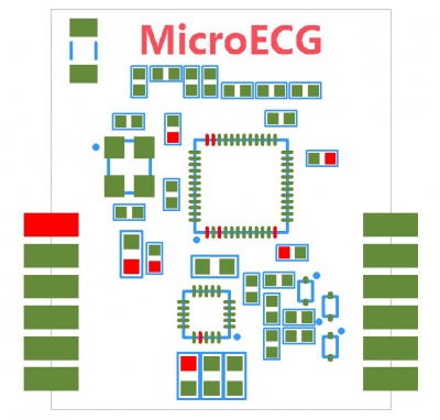
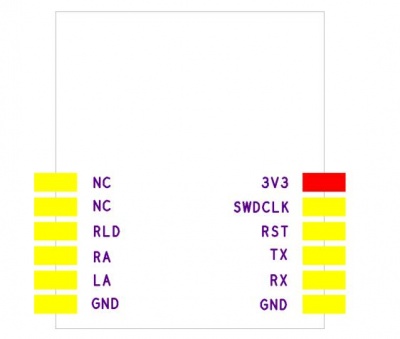
| 1 | 3V3 |
| 2 | SWDCLK |
| 3 | SWDIO/RST |
| 4 | TXD(P0.12) |
| 5 | RXD(P0.11) |
| 6 | GND |
| 7 | GND |
| 8 | LA |
| 9 | RA |
| 10 | RLD |
| 11 | NC |
| 12 | NC |
Interface Functions
- SWDCLK: SWD interface clock line
- SWDIO/RST: SWD interface data line
- RXD/TXD: serial, support AT command
- LA: left arm signal input pin
- RA: right arm signal input pin
- RLD: right arm drive feedback output pin
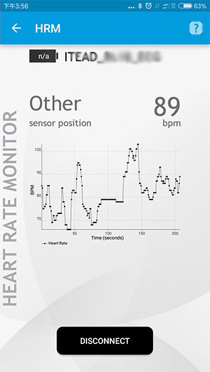
1.Power up this module with 3.3V. And use ECG Limb Clamp (IM161025001) and ECG Lead Wire (IM161025002) to clamp your arm.
2.Run the BLE app on the phone. Click and turn into the “HRM” mode and then connect to the “ITEAD_BL18_ECG” device.
3.Just wait a while and the heart rate will be displayed.
AT commands:
1.“AT\r”
This command is a string and used to test the UART connection.
When the UART is working , “OK\r\n” will be returned.
2.“ATdataTypeR\r”
This command is a string and used to set the data type to row data.
When the command runs successfully , "Type:R\nOK\r\n" will be returned.
This command can not run successfully when the “ATstartRead\r” is running.
3.“ATdataTypeH\r”
This command is a string and used to set the data type to heart rate.
When this command runs successfully, "Type:H\nOK\r\n" will be returned.
This command can not run successfully when the “ATstartRead\r” is running.
4.“ATdataType?\r” This command is a string and used to get the current data type.
When this command runs successfully, and the current data type is row data, then "Type:R\nOK\r\n" will be returned.
When this command runs successfully, and the current data type is heart rate, then "Type:H\nOK\r\n" will be returned.
This command can not run successfully when the “ATstartRead\r” is running.
5.“ATtestCon\r”
This command is a string and used to test the connection of the ECG cable.
When the hardware connection of ECG cable is ok, “OK\r\n” will be returned.
When the hardware connection of ECG cable is not ok, “ERROR\r\n” wii be returned.
6.“ATstartRead\r”
This command is a string and used to get the data from UART.
When the hardware connection of ECG cable is not ok, “ERROR\r\n” wiil be returned.
When the hardware is ok, “OK\r\n” will be returned firstly, and then the data will be transported continuously as soon as the data itself is updated.
7.“ATstopRead\r”
This command is a string and used to stop the reading action through UART.
When this command runs successfully, “OK\n\r” will be returned and the reading action will stop.
Useful Link
File:IM161018001-MicroECG-PCBVIEW.pdf
File:IM161018001-MicroECG-schematic.pdf
 Notice


