Difference between revisions of "IDSG101"
m (→Overview) |
m (→How to Upgrade Firmware) |
||
| (20 intermediate revisions by the same user not shown) | |||
| Line 7: | Line 7: | ||
With a high solution 3 inch full color LCD and resistive touch screen, IDSG101 has an expressive English interface, which helps users to get started using this device easily. IDSG101's firmware can be upgraded, and we will perfect this device gradually according to users' feedback. | With a high solution 3 inch full color LCD and resistive touch screen, IDSG101 has an expressive English interface, which helps users to get started using this device easily. IDSG101's firmware can be upgraded, and we will perfect this device gradually according to users' feedback. | ||
| − | Go shopping [IDSG101(IM141013001)] | + | '''Please visit [http://support.iteadstudio.com/discussions/forums/1000227085 its topic] in our forum to know more discussion about this product.''' |
| + | |||
| + | Go shopping [http://imall.iteadstudio.com/im141013001.html IDSG101(IM141013001)] | ||
==Features== | ==Features== | ||
| Line 21: | Line 23: | ||
==Specification== | ==Specification== | ||
*'''Waveforms''' | *'''Waveforms''' | ||
| − | {| border="1" width=" | + | {| border="1" width="600" |
| Standard Waveform ||Sine, Square, Triangle, Sawtooth rise , Sawtooth fall, Sinc ,Noise, Exponential rise, Exponential fall, Positive full-wave, Negative full-wave, Positive half-wave, Negative half-wave, Gaussian ,DC | | Standard Waveform ||Sine, Square, Triangle, Sawtooth rise , Sawtooth fall, Sinc ,Noise, Exponential rise, Exponential fall, Positive full-wave, Negative full-wave, Positive half-wave, Negative half-wave, Gaussian ,DC | ||
|- | |- | ||
| Line 109: | Line 111: | ||
|} | |} | ||
| − | == | + | ==Basic Operation== |
| − | + | ||
| − | + | ||
| − | + | ||
| − | + | ||
| − | + | ||
| − | + | ||
| − | + | ||
| − | == | + | ===Connectors=== |
| − | + | ||
| − | + | ||
| + | [[File:IDSG101_0.jpg|400px]] | ||
| + | [[File:IDSG101_1.jpg|400px]] | ||
| + | |||
| + | |||
| + | '''Sync Connector''': Sync Output. When you out put a standard wave through this connector, you will see a TTL wave (low level 0V, high level 5V) that have the same frequency and phrase with the standard wave you choose. It can be the clock or trigger signal of digital system when sync connector connect with digital system. | ||
| + | '''Output Connector''': Waveform output end. With an output Impedance of 50Ω, IDSG101 can output standard/arbitrary waveform though this connector. Please note that high voltage cannot be accessed to this connector. | ||
| + | |||
| + | '''Micro USB''': For power supply and computer connecting. | ||
| + | |||
| + | '''Extension Connector''': This connector includes UART, interface of trigger input/output. | ||
| + | |||
| + | |||
| + | ===Operation Interface=== | ||
| + | |||
| + | The operation interface pictures show as below. Since IDSG101 adopts a resistive screen, you’d better use touch pen to do operating. | ||
| + | |||
| + | Start interface (Support two languages: Chinese and English) | ||
| + | |||
| + | [[File:IM141013001_41.png|400px]] | ||
| + | |||
| + | |||
| + | Function set | ||
| − | |||
[[File:IM141013001i.png|400px]] | [[File:IM141013001i.png|400px]] | ||
| + | Arbitrary waveform choosing | ||
| − | |||
[[File:IM141013001k.png|400px]] | [[File:IM141013001k.png|400px]] | ||
| − | + | Burst interface | |
| − | [[File:IM141013001l.png|400px]] | + | |
| + | [[File:IM141013001_42.png|400px]] | ||
| + | |||
| + | |||
| + | Sweep interface | ||
| + | |||
| + | [[File:IM141013001_43.png|400px]] | ||
| + | |||
| + | |||
| + | System set | ||
| + | |||
| + | [[File:IM141013001l.png]] | ||
| + | |||
| + | ===IDSG101 works as a virtual U disk=== | ||
| + | |||
| + | IDSG101 has a 128M memory that can storage the whole system and your arbitrary waveform files. Connect IDSG101 to your computer via USB cable, and then you need to press the “enter USB flash disk mode” button to make your computer identify this device. | ||
| + | |||
| + | [[File:IDSG101_2.png|400px]] | ||
| + | |||
| + | When they connect together, you can find two folders in the removable disk: <system> and <arb_wave>. | ||
| + | |||
| + | System folder cannot be modified. And you can put your waveform files in the folder <arb_wave>. Please note that IDGS101 supports wvt file only. If not this format, you’d better transform it to. | ||
| + | |||
| + | ==How to generate wvt waveform files== | ||
| + | IDSG101 supports wvt waveform files only, we offer two methods to generate a wvt files. | ||
| + | |||
| + | *Use Agilent Waveform Editor & Harmonic Wave Creator: | ||
| + | http://blog.iteadstudio.com/idsg101-manual-how-to-transform-the-arbitrary-waveform-format-part-1/ | ||
| + | *Use MATLAB: | ||
| + | http://blog.iteadstudio.com/idsg101-manual-how-to-transform-the-arbitrary-waveform-format-part-2/ | ||
| + | |||
| + | ==How to Upgrade Firmware== | ||
| + | |||
| + | Firmware is keeping upgrading to fix the bugs and perfect the product. | ||
| + | |||
| + | Step 1: Download the firmware(update.bin file) | ||
| + | *Firmware update in 2015-04-24 [[:File:update 1.0.2build690.zip]] | ||
| + | *Firmware update in 2014-12-29 [[:File:update 1.0.2build627.zip]] | ||
| + | *Firmware update in 2014-10-08 [[:File:update 1.0.2build539.zip]] | ||
| + | Step 2: Connect IDSG101 to you PC, and enter into the Virtual U Disk mode. | ||
| + | |||
| + | Step 3: Drag the firmware into the root directory of U disk. | ||
| + | |||
| + | Step 4: Exit the Virtual U Disk mode, at this time, IDSG101 will detect the upgrade firmware automatically. | ||
| + | |||
| + | Step 5: When you see the picture as below, please touch the button to upgrade. | ||
| + | |||
| + | Step 6: When upgrading the firmware, don't do any operation on this device, and don't cut off the power, otherwise, the upgrade will fail. | ||
| + | |||
| + | [[File:IDSG101_firmware_1.png]] | ||
| + | |||
| + | [[File:IDSG101_firmware_2.png]] | ||
| + | |||
| + | Step 7: To ensure the upgrade of firmware is successful, you can check your firmware information in ''System -> About'' | ||
| + | |||
| + | ==Arbitrary waveform display in IDSG101== | ||
| + | [[File:IM141013001_11.jpg|500px]] | ||
| + | [[File:IM141013001_12.jpg|500px]] | ||
| + | [[File:IM141013001_13.jpg|500px]] | ||
| + | [[File:IM141013001_14.jpg|500px]] | ||
| + | [[File:IM141013001_15.jpg|500px]] | ||
| + | [[File:IM141013001_16.jpg|500px]] | ||
| + | [[File:IM141013001_17.jpg|500px]] | ||
| + | [[File:IM141013001_18.jpg|500px]] | ||
| + | [[File:IM141013001_19.jpg|500px]] | ||
| + | [[File:IM141013001_20.jpg|500px]] | ||
| + | [[File:IM141013001_21.jpg|500px]] | ||
| + | [[File:IM141013001_22.jpg|400px]] | ||
| + | [[File:IM141013001_23.jpg|500px]] | ||
| + | [[File:IM141013001_24.jpg|500px]] | ||
| + | [[File:IM141013001_25.jpg|500px]] | ||
| + | [[File:IM141013001_26.jpg|500px]] | ||
| + | [[File:IM141013001_27.jpg|500px]] | ||
| + | [[File:IM141013001_28.jpg|500px]] | ||
| + | [[File:IM141013001_29.jpg|500px]] | ||
| + | [[File:IM141013001_30.jpg|500px]] | ||
| + | [[File:IM141013001_31.jpg|500px]] | ||
| + | [[File:IM141013001_32.jpg|500px]] | ||
| + | [[File:IM141013001_33.jpg|500px]] | ||
| + | [[File:IM141013001_34.jpg|500px]] | ||
| + | [[File:IM141013001_35.jpg|500px]] | ||
| + | [[File:IM141013001_37.jpg|500px]] | ||
| + | [[File:IM141013001_38.jpg|500px]] | ||
| + | [[File:IM141013001_39.jpg|500px]] | ||
| + | [[File:IM141013001_40.jpg|500px]] | ||
| + | |||
| + | ==Internal PCB== | ||
| + | |||
| + | [[File:IM141013001_1.jpg|500px]] | ||
| + | [[File:IM141013001_2.jpg|500px]] | ||
| − | == | + | ==Useful Link & Download== |
| + | *Hand-draw waveform output tutorial--http://blog.iteadstudio.com/idsg101-manual-how-to-transform-the-arbitrary-waveform-format-part-1/ | ||
| + | *Waveform file converter--[[:File:HW_creator_V1.1.zip]] | ||
Latest revision as of 02:50, 22 May 2015
Contents
Overview
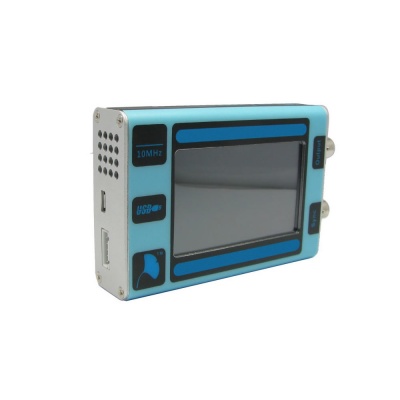
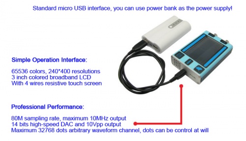
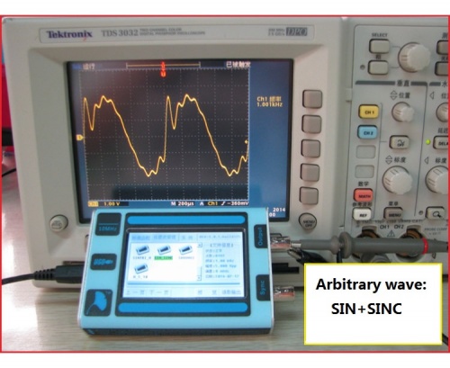
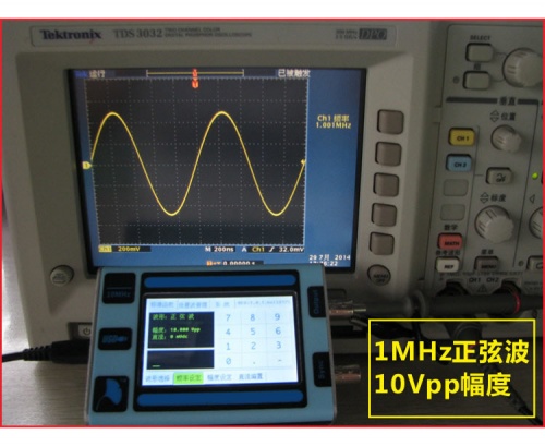
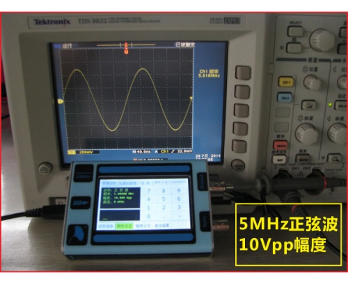
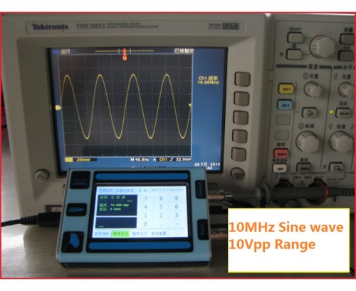
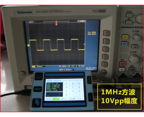
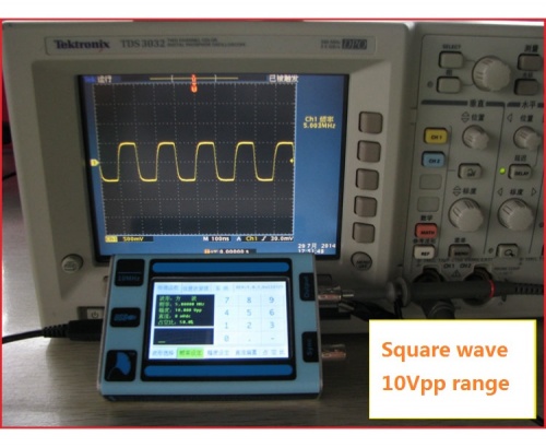
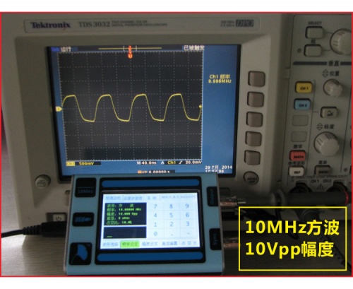
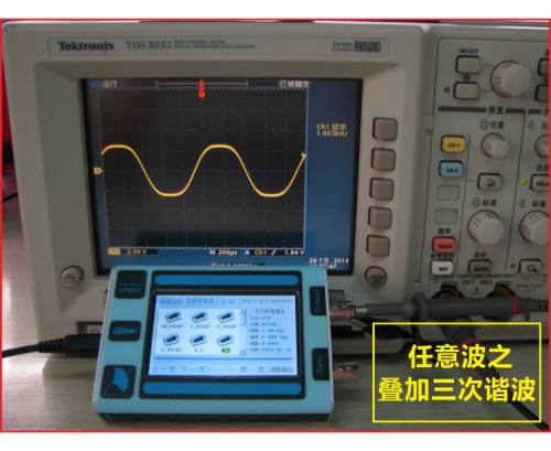
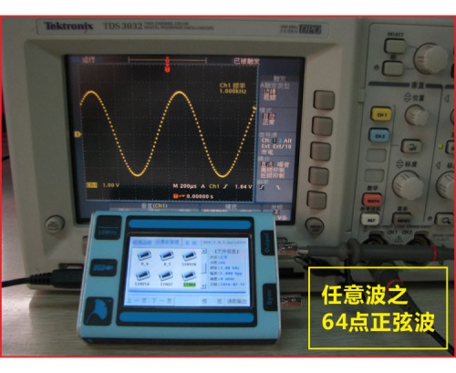
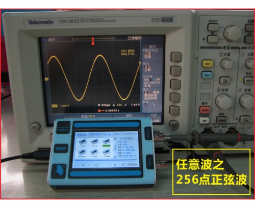
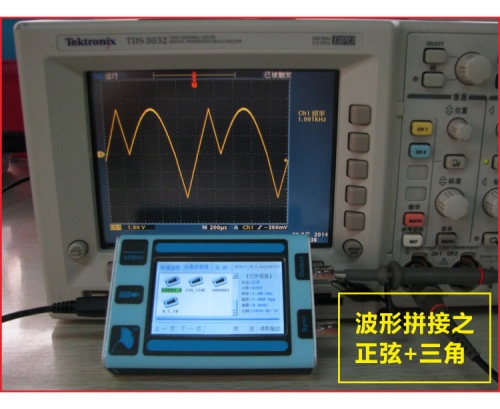
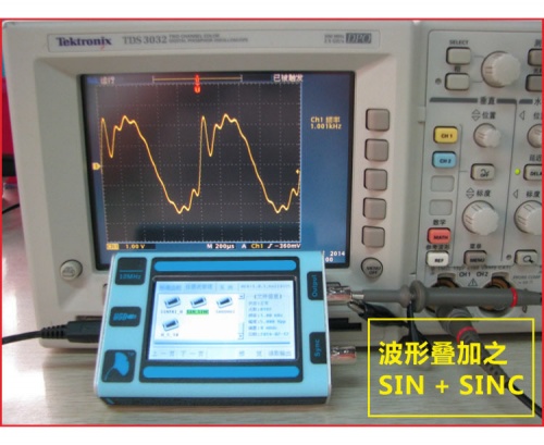
Based on several advanced technologies, IDSG101 can realize some unique functions that common desktop devices have in a small size. Though this device is as small as your hand, it can realize 80M sampling rate, maximum 10 MHz and 10Vpp range output.
IDSG101 is capable of full functional arbitrary waveform management and output. Because the data of arbitrary waveform adopts the files system management and the protocol is fully open to users, users can manage several arbitrary waveform files easily by the technology of virtual U disk.
With a high solution 3 inch full color LCD and resistive touch screen, IDSG101 has an expressive English interface, which helps users to get started using this device easily. IDSG101's firmware can be upgraded, and we will perfect this device gradually according to users' feedback.
Please visit its topic in our forum to know more discussion about this product.
Go shopping IDSG101(IM141013001)
Features
- 65536 colors, 240*400 solutions, 3 inch colored broadband LCD, and 4 wire resistive touch screen.
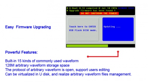
- Built-in 15 kinds of commonly used waveform, 128 m arbitrary waveform storage space
- The protocol of arbitrary waveform is open, support users editing
- Can be virtualized in U disk, and realize arbitrary waveform files management.
- 80M sampling rate, maximum 10MHz output
- 14 bits high-speed DAC and 10Vpp output
- Maximum 32768 dots arbitrary waveform channel, dots can be control at will
- 5V power supply, 200mA~400mA current consumption
Specification
- Waveforms
| Standard Waveform | Sine, Square, Triangle, Sawtooth rise , Sawtooth fall, Sinc ,Noise, Exponential rise, Exponential fall, Positive full-wave, Negative full-wave, Positive half-wave, Negative half-wave, Gaussian ,DC |
| Sample Rate | 80 MS/s |
| Vertical Resolution | 14 bit |
| Arbitrary Waveform Length | 2 to 32 K points |
| Built-in storage | 128 M |
- Frequency Characteristics
| Output range | Sine | 1 mHz ~ 10 MHz |
| Square | 1 mHz ~ 10 MHz | |
| Others | 1 mH ~ 1 MHz | |
| Resolution | 1mHz | |
| Accuracy | 50 ppm | |
- Voltage characteristics
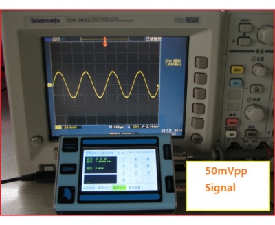
| Output range | 10 mVpp ~ 10 Vpp |
| Resolution | 12 bit |
| Accuracy | 8% of Setpoint |
| Offset Range | ±5V |
| Amplitude Flatness | ≥0.3 dB |
- Square characteristics
| Duty Cycle | 0.1%~99.9% (1mHz~1MHz) |
| lock 50% (1MHz~10MHz) | |
| Rise/Fall Time | <20 ns |
| Overshoot | <5% |
- General
| output Impedance | 50 Ω |
| Ramp Symmetry | 0.1%~99.9% |
| Sync signal | TTL ( 4.8 V~5.2 V ) |
| Power requirements | DC ( 4.75 V~5.25 V, < 400 mA) |
| Display characteristics | 3-inch, 240x400 resolution |
| Dimensions (L x W x H) | 116 mmx76 mmx26 mm |
| Weight | 180 g |
Basic Operation
Connectors
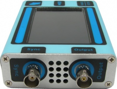
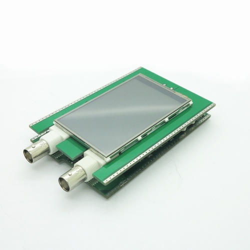
Sync Connector: Sync Output. When you out put a standard wave through this connector, you will see a TTL wave (low level 0V, high level 5V) that have the same frequency and phrase with the standard wave you choose. It can be the clock or trigger signal of digital system when sync connector connect with digital system.
Output Connector: Waveform output end. With an output Impedance of 50Ω, IDSG101 can output standard/arbitrary waveform though this connector. Please note that high voltage cannot be accessed to this connector.
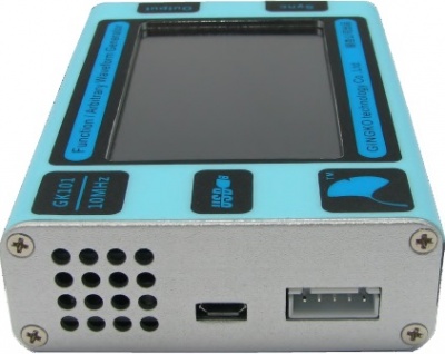
Micro USB: For power supply and computer connecting.
Extension Connector: This connector includes UART, interface of trigger input/output.
Operation Interface
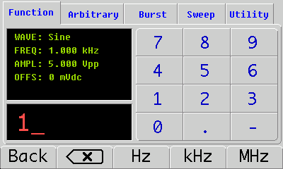
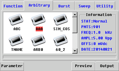
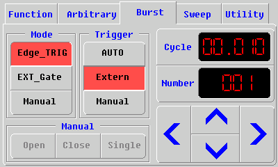
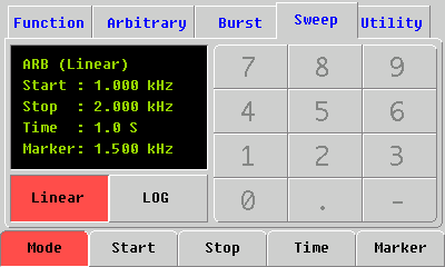
The operation interface pictures show as below. Since IDSG101 adopts a resistive screen, you’d better use touch pen to do operating.
Start interface (Support two languages: Chinese and English)
Function set
Arbitrary waveform choosing
Burst interface
Sweep interface
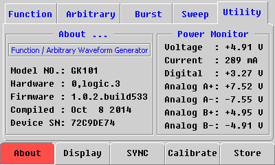
System set
IDSG101 works as a virtual U disk
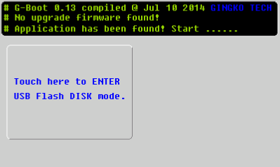
IDSG101 has a 128M memory that can storage the whole system and your arbitrary waveform files. Connect IDSG101 to your computer via USB cable, and then you need to press the “enter USB flash disk mode” button to make your computer identify this device.
When they connect together, you can find two folders in the removable disk: <system> and <arb_wave>.
System folder cannot be modified. And you can put your waveform files in the folder <arb_wave>. Please note that IDGS101 supports wvt file only. If not this format, you’d better transform it to.
How to generate wvt waveform files
IDSG101 supports wvt waveform files only, we offer two methods to generate a wvt files.
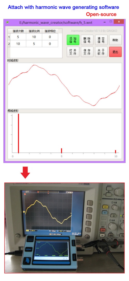
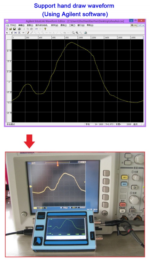
- Use Agilent Waveform Editor & Harmonic Wave Creator:
http://blog.iteadstudio.com/idsg101-manual-how-to-transform-the-arbitrary-waveform-format-part-1/
- Use MATLAB:
http://blog.iteadstudio.com/idsg101-manual-how-to-transform-the-arbitrary-waveform-format-part-2/
How to Upgrade Firmware
Firmware is keeping upgrading to fix the bugs and perfect the product.
Step 1: Download the firmware(update.bin file)
- Firmware update in 2015-04-24 File:update 1.0.2build690.zip
- Firmware update in 2014-12-29 File:update 1.0.2build627.zip
- Firmware update in 2014-10-08 File:update 1.0.2build539.zip
Step 2: Connect IDSG101 to you PC, and enter into the Virtual U Disk mode.
Step 3: Drag the firmware into the root directory of U disk.
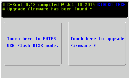
Step 4: Exit the Virtual U Disk mode, at this time, IDSG101 will detect the upgrade firmware automatically.
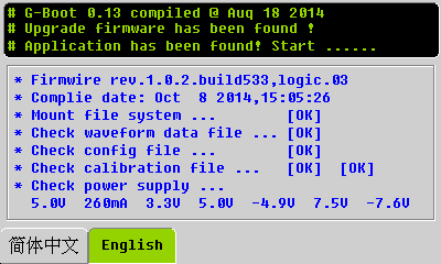
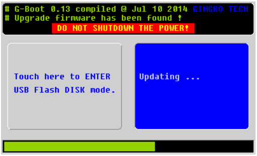
Step 5: When you see the picture as below, please touch the button to upgrade.
Step 6: When upgrading the firmware, don't do any operation on this device, and don't cut off the power, otherwise, the upgrade will fail.
Step 7: To ensure the upgrade of firmware is successful, you can check your firmware information in System -> About
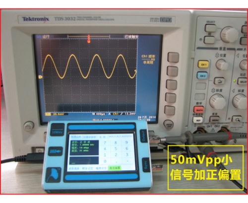
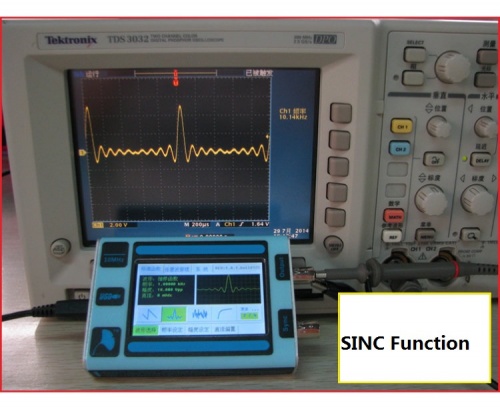
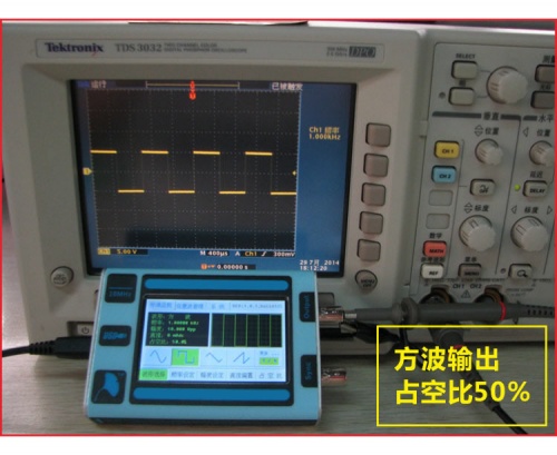
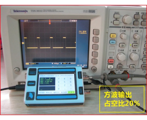
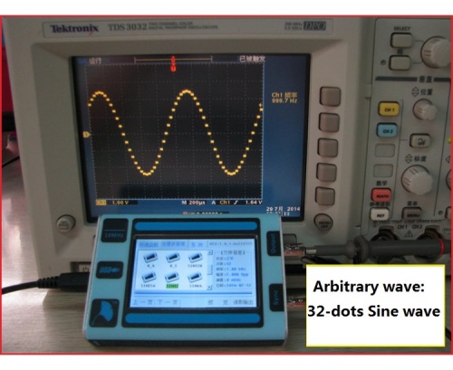
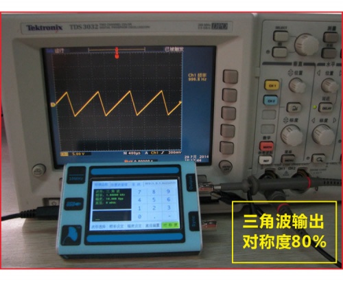
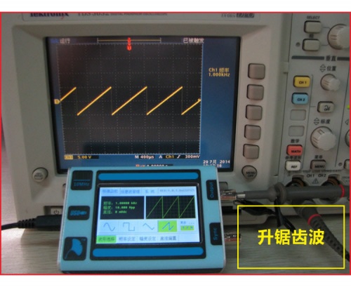
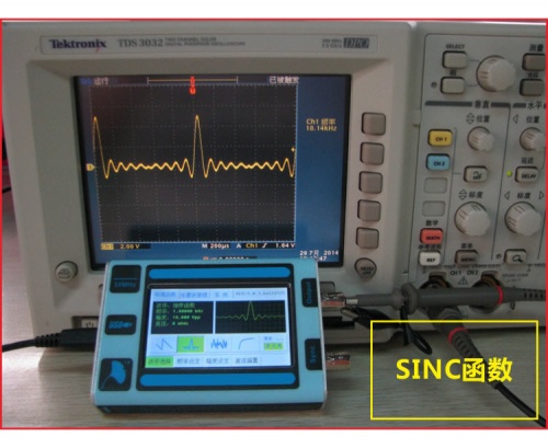
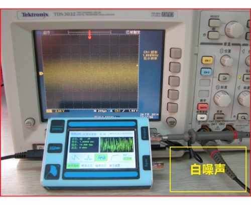
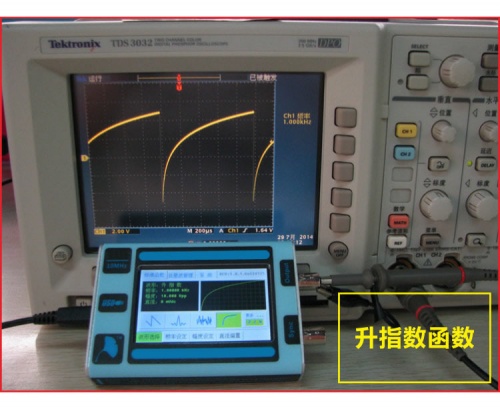
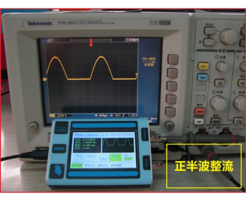
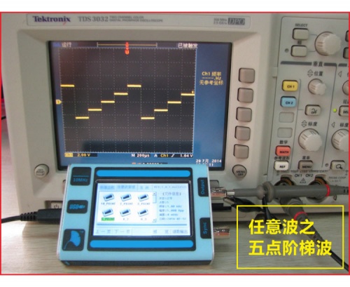
Arbitrary waveform display in IDSG101
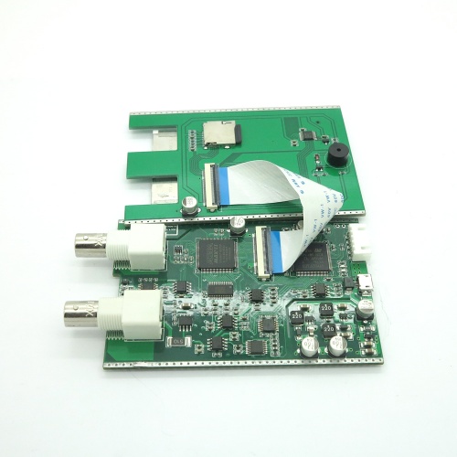
Internal PCB
Useful Link & Download
- Hand-draw waveform output tutorial--http://blog.iteadstudio.com/idsg101-manual-how-to-transform-the-arbitrary-waveform-format-part-1/
- Waveform file converter--File:HW_creator_V1.1.zip
 Notice