Difference between revisions of "ITEAD A10/A20 Core"
(→Over View) |
m (→Download) |
||
| (10 intermediate revisions by 3 users not shown) | |||
| Line 1: | Line 1: | ||
| + | '''Not Recommended for New Designs (NRND) | ||
| + | |||
| + | '''Replaced By AW204X– The device has the SAME FUNCTIONALITY as the compared device, but is not pin-for-pin equivalent. | ||
| + | |||
| + | '''ITEAD does not recommend using this part in a new design. This product continues to be in production to support existing customers.''' | ||
| + | |||
| + | |||
| + | |||
==Over View== | ==Over View== | ||
| Line 6: | Line 14: | ||
ITEAD A20 Core is the upgraded version of A10 Core, which adopts dual-core and supports dominant frequency up to 1GHz. Other configurations are completely same with A10 Core, and pins of the two version are 100% compatible, thus hardware can be replaced directly. | ITEAD A20 Core is the upgraded version of A10 Core, which adopts dual-core and supports dominant frequency up to 1GHz. Other configurations are completely same with A10 Core, and pins of the two version are 100% compatible, thus hardware can be replaced directly. | ||
| − | To use ITEAD A10/A20 CORE for [[project]] development, design of complex multi-layer high-speed circuit is not required, as you only need to provide it with a stable 5V power supply and connect the pins on the module to the corresponding socket (such as HDMI, Micro-SD card, USB, etc.), or to the relevant circuit bus (such as I / O ports, UART, SPI, etc.). With design of such functional board, the difficulty will be decreased compared to directly using chips with SDRAM, FLASH, power circuit and functional circuit for the layout and the [[project]] development cycle will also be greatly reduced. | + | To use [[ITEAD A10/A20 Core|ITEAD A10/A20 CORE]] for [[project]] development, design of complex multi-layer high-speed circuit is not required, as you only need to provide it with a stable 5V power supply and connect the pins on the module to the corresponding socket (such as HDMI, Micro-SD card, USB, etc.), or to the relevant circuit bus (such as I / O ports, UART, SPI, etc.). With design of such functional board, the difficulty will be decreased compared to directly using chips with SDRAM, FLASH, power circuit and functional circuit for the layout and the [[project]] development cycle will also be greatly reduced. |
Go shopping [http://imall.iteadstudio.com/itead-a10-a20-core.html ITEAD A10/A20 Core (IM130808001)] | Go shopping [http://imall.iteadstudio.com/itead-a10-a20-core.html ITEAD A10/A20 Core (IM130808001)] | ||
==Specifications== | ==Specifications== | ||
| + | We offer the [[product]] with different configurations for customers to choose. The following table shows specifications of ITEAD Core V1. | ||
{| border="1" | {| border="1" | ||
| + | | CPU||Allwinner A10||Allwinner A10||Allwinner A20||Allwinner A20 | ||
|- | |- | ||
| − | | | + | | RAM capacity||1G||1G||1G||1G |
| − | | | + | |- |
| + | | NAND FLASH||0||4G||0||4G | ||
| + | |- | ||
| + | | SKU||IM130808002||IM130808003||IM130808005||IM130808006 | ||
| + | |} | ||
| + | |||
| + | ITEAD Core V2 is coming soon. | ||
| + | |||
| + | {| border="1" | ||
|- | |- | ||
| Line 37: | Line 55: | ||
|- | |- | ||
! Item !! Typical Value !! Unit | ! Item !! Typical Value !! Unit | ||
| − | |||
| − | |||
| − | |||
| − | |||
| − | |||
| − | |||
|- | |- | ||
| Voltage at I/O port || 3.3||V | | Voltage at I/O port || 3.3||V | ||
| Line 65: | Line 77: | ||
==Download== | ==Download== | ||
| − | + | * [[:File:SCH_IM130808001.pdf |Schematic]] | |
* Datasheet ftp://imall.iteadstudio.com/ARM/IM130808001/DS_IM130808001.pdf | * Datasheet ftp://imall.iteadstudio.com/ARM/IM130808001/DS_IM130808001.pdf | ||
| − | |||
* Pinmap ftp://imall.iteadstudio.com/ARM/IM130808001/A10_A20_Core_pinmap_130903.pdf | * Pinmap ftp://imall.iteadstudio.com/ARM/IM130808001/A10_A20_Core_pinmap_130903.pdf | ||
* Eagle library file http://blog.iteadstudio.com/download/88/ | * Eagle library file http://blog.iteadstudio.com/download/88/ | ||
| + | * Download OS and OS installation tutorial: http://wiki.iteadstudio.com/Download | ||
Latest revision as of 09:30, 9 December 2016
Not Recommended for New Designs (NRND)
Replaced By AW204X– The device has the SAME FUNCTIONALITY as the compared device, but is not pin-for-pin equivalent.
ITEAD does not recommend using this part in a new design. This product continues to be in production to support existing customers.
Contents
Over View
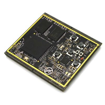
ITEAD A10 CORE is a minimum system module based on design of A10 chip. With ARM Cortex A8 core, it supports maximum frequency up to 1GHz. The module is equipped with 1G DDR3 memory and 4G FLASH. The digital circuit section and the overall power design of SDRAM on the module has been completed, so it can work directly after powering up with a stable 5V supply.
ITEAD A20 Core is the upgraded version of A10 Core, which adopts dual-core and supports dominant frequency up to 1GHz. Other configurations are completely same with A10 Core, and pins of the two version are 100% compatible, thus hardware can be replaced directly.
To use ITEAD A10/A20 CORE for project development, design of complex multi-layer high-speed circuit is not required, as you only need to provide it with a stable 5V power supply and connect the pins on the module to the corresponding socket (such as HDMI, Micro-SD card, USB, etc.), or to the relevant circuit bus (such as I / O ports, UART, SPI, etc.). With design of such functional board, the difficulty will be decreased compared to directly using chips with SDRAM, FLASH, power circuit and functional circuit for the layout and the project development cycle will also be greatly reduced.
Go shopping ITEAD A10/A20 Core (IM130808001)
Specifications
We offer the product with different configurations for customers to choose. The following table shows specifications of ITEAD Core V1.
| CPU | Allwinner A10 | Allwinner A10 | Allwinner A20 | Allwinner A20 |
| RAM capacity | 1G | 1G | 1G | 1G |
| NAND FLASH | 0 | 4G | 0 | 4G |
| SKU | IM130808002 | IM130808003 | IM130808005 | IM130808006 |
ITEAD Core V2 is coming soon.
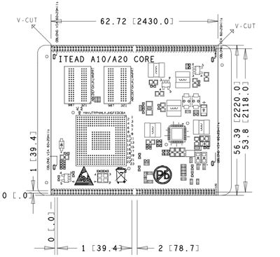
| PCB Size | 62.72 X 56.39 X 1.61mm |
| Indicator | 3V3 |
| Interface | 4 groups of 2*30 1mm pitched female headers break out all I/O interfaces |
| Input voltage | 4.85~5.15VDC, typical value of 5VDC |
Electrical characteristics
| Item | Typical Value | Unit |
|---|---|---|
| Voltage at I/O port | 3.3 | V |
| Input voltage | 4.85~5.15 | VDC |
| Working current(low load) | 350 | mA |
|  Working current(high load) | 600 | mA |
Note 1: There are two versions of NAND FLASH capacity: 0G and 4G.
Note 2: Working current (low load) refers to the working current when no other operations are done (CPU occupancy rate of about 2%) after entering ITEAD OS instead of the minimum working current; SATA hard drive is a big power consumer, working current will reach up to 550mA when connecting2.5-inch SATA hard drive in the low load condition. Note 3: Working current (high load) refers to the working current when CPU is doing super pi operation (CPU occupancy rate of about 98%) after entering ITEAD OS instead of the maximum working current.
Hardware
Appearance
Download
- Schematic
- Datasheet ftp://imall.iteadstudio.com/ARM/IM130808001/DS_IM130808001.pdf
- Pinmap ftp://imall.iteadstudio.com/ARM/IM130808001/A10_A20_Core_pinmap_130903.pdf
- Eagle library file http://blog.iteadstudio.com/download/88/
- Download OS and OS installation tutorial: http://wiki.iteadstudio.com/Download
 Notice

