4-20mA Sensor Brick
Contents
Overview
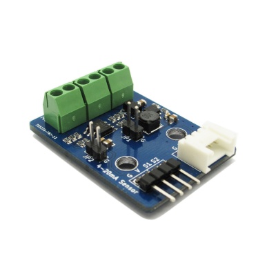
4~20mA Sensor Brick is an electronic brick module that can be used to test electronic current loop from 4mA to 20mA and support type2,3,4 current output. With a 5V to 24V DC-DC power boost convertor, its max current output can be 150mA, which can be for equipment use.
Go shopping 4-20mA Sensor Brick(IM140819001)
Features
- Compatible with the mainstream 2.54 and 4-pin Grove interface in market
- Compatible with type2,3,4 electronic current loop
- With use of M4 standard fixed holes, compatible with M4-standard kits such as Lego and Makeblock.
Specification
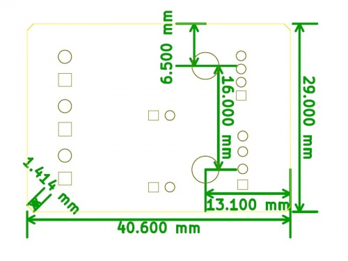
| PCB size | 40.6mm X 29mm X 1.6mm |
| Power supply | 5V DC |
| Compatible interfaces | 2.54 4-pin interface and 4-pin Grove interface(1) |
Electronic Characteristics
| Parameter | Min. | Typical | Max. | Unit |
| Power supply | 4.5 | 5 | 5.5 | VDC |
| Input measurement current | 4 | - | 20 | mA |
| Output Current(DCDC) | - | - | 150 | mA |
Hardware
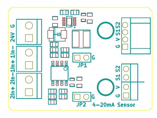
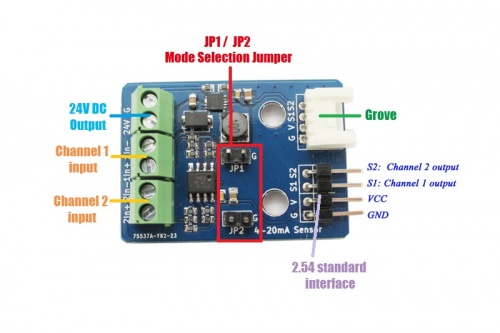
| JP1 | JP2 | |
| Connected | CH1 Type 2/3 | CH2 Type 2/3 |
| Disconnected | CH1 Type4 | CH2 Type4 |
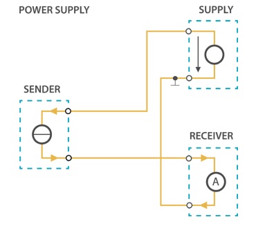
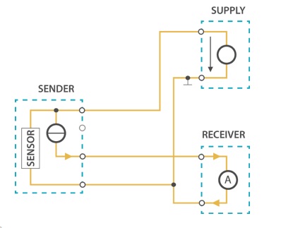
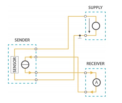
Loop current type
- Type 2 loop current
- Type 3 loop current
- Type 4 loop current
The relationship between output voltage and input current in channel 1,2
In theory, their relationship can be described into this formula:
Vout1 = R1 * Iin1 * 2
Vout2 = R2 * Iin2 * 2
R1=R2=100ohm
Note: error ±2% in practical test.
Instruction
- 1. Upload the demo File:4_20mA_demo.zip into Iteaduino UNO
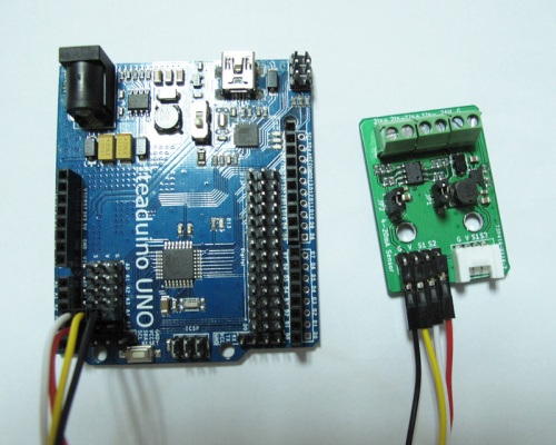
- 2. Connect the sensor brick and UNO as following picture. S1->A4 and S2->A5.
- 3. Measure current loop
- When access in type2,3 loop current, please connect JP1 or JP2, both 1In- and 2In- is equal to connecting ground, 1In+ and 2In+ are connected with the current pins to be measured.
- When access in type4 loop current, connect the input end to 1In+ or 2In+, the output end to 1In- or 2In-, and unplug JP1 or JP2 simultaneously.
 Notice