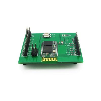
BT BoosterPack
Contents
Overview
BT Boosterpack is a serial port Bluetooth shield for LaunchPad. BT Boosterpack expand the LaunchPad with Bluetooth communication functions, supports master and slave mode. It will be much easier to make your cell phone or laptop to talk with LaunchPad now.
Features
- LaunchPad / LaucnchPad XL / LaunchPad XLL compatible, and stackable for other BoosterPack
- Up to10m communication distance in house without obstacle
- UART interface (TTL) with programmable baud rate (SPP firmware installed)
- Default baud rate: 38400(CMD MODE) / 9600(DATA MODE), data bits: 8, stop bit: 1, Parity: No parity
- Default PINCODE: 1234
- A full set of configuration commandsOn board PCB antenna
- FCC ID certificated
Specifications
| Microprocessor | CSR BC417 |
| PCB size | 53.34mm X 43.18mm X 1.6mm |
| Indicators | PWR, status, link |
| Power supply | 3.3V DC |
| IO | 2 |
| Communication Protocol | UART/Bluetooth 2.0 |
Electrical Characteristics
| Specification | Min | Type | Max | Unit |
| Power Voltage | 3 | 3.3 | 3.6 | VDC |
| Input Voltage VH(Target Voltage = 3.3V ) | 3 | 3.3 | 3.6 | V |
| Input Voltage VL: | -0.3 | 0 | 0.5 | V |
| Current Consumption | 20 | 45 | mA |
Hardware

Figure 1 Top view of BT shield V2.2
Pin Map
| MODE | P1.0 |
| TX | P1.1 |
| RX | P1.2 |
| BT_Ret | P1.3 |
| Status | P1.4 |
| Link | P1.5 |
| EB6 | P1.6 |
| EB7 | P1.7 |
Mode Button
The Mode Button is connected with PIO11 of HC-05. When Mode Button is pressed, the PIO11 of HC-05 will be in HIGH level, and the module will change to AT command mode.
If Mode Button is pressed in different status, HC-05 module will enter different AT mode.
AT command mode 1:
When the Mode Button is pressed after power on or reset (when the boosterpack is working in DATA mode), the boosterpack will enter AT command mode 1. The UART baud rate in AT command mode 1 is the same as Data mode, default 9600bps.
AT command mode 2:
When the Mode Button is pressed before power on, and hold until power on or reset, the boosterpack will enter AT command mode 2. The UART baud rate in AT command mode 2 is 38400bps.
The PIO11 pin is also connect to the P1.0 of LaunchPad, users can use the LanchPad to change the mode of BT Boosterpack in any time.
Reset Button
The Reset Button is connected with reset pin of HC-05. When Reset Button is pressed, the PIO11 of HC-05 will be in LOW level.
When Reset Button is pressed, the BT BoosterPack will reset.
The PIO11 pin is also connect to the P1.3 of LaunchPad, users can use the LaunchPad to reset the BT boosterpack in any time.
PWR LED
PWR LED is the indicator of power supply. When power on, it will keep lighting.
Status LED
The Status LED is connected to PIO8 of HC-05. It is the indicator of the BT Boosterpack working mode.
If the Status LED blinks at 1Hz, BT Boosterpack is in AT command mode 2.
If the Status LED blinks at 2Hz, BT Boosterpack is in AT command mode 1 or in pairing mode (in this mode, cannot transfer data yet).
If the Status LED double blinks, BT Boosterpack has finished pairing, and enter DATA mode, it’s ready for data transfer.
The PIO8 pin is also connect with the P1.4 pin of LaunchPad, users can use the LaunchPad to read the BT Boosterpack working mode.
Link LED
The Link LED is connected to PIO9 of HC-05, and it’s the indicator of Link/Connection status.
- If the Link LED is light on, BT Boostpack is connected with some other
Bluetooth device, and ready for data transfer.
- If the Link LED is light off, BT Boostpack is not connected with any other
device.
The PIO9 pin is also connect with P1.5 of Launch Pad, users can use the LaunchPad to read the link/connection status of BT Boosterpack.
 Notice