Arduino GPS shield
Contents
Overview
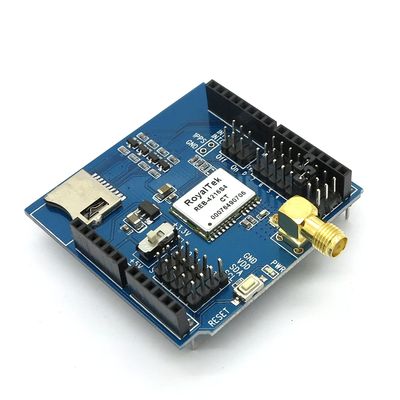
Arduino GPS shield is a GPS module breadout board designed for Global Positioning System receiver with SD interface. It is easy to use for recording the position data into SD card. 5V/3.3V compatible operation voltage level make it compatible with Arduino boards, leaf maple, IFlat32 and other arduino compatible boards.
It's based on RoyalTek REB-4216 GPS module , and the footprints is compatible with Arduino/MEGA boards. The regular GPS pins (RX, TX) can be connected to D0-D7 of Arduino.
Adding GPS to your Arduino has never been easier. Multiple GPS receivers attach easily to the shield, and with the example sketch (check below), you will be able to locate your exact position within a few meters. Here's where we are. GPS also gives you amazingly accurate time! It’s suitable for the following applications with Arduino or Arduino compatible boards :
- Automotive navigation
- Personal positioning
- Fleet management
- Marine navigation
Go shopping Arduino GPS shield (IM120417017)
Features
- With Micro SD interface
- Active antenna design with high receive sensitivity, compatible
normal antenna
- Extremely fast time to first fix at low signal level
- UART interface
- Operation temperature: -40℃ ~ +85℃
Specifications
| PCB size | 55.88mm X 54.1mm X 1.6mm |
| Indicators | PWR |
| Power supply | compatible with Arduino |
| Communication Protocol | UART |
| RoSH | Yes |
Electrical Characteristics
| Parameter | Min. | Typical | Max. | Unit |
| Power voltage | 4.5 | 5 | 5.5 | VDC |
| Input voltage VH | 3 | 5.5 | V | |
| Input voltage VL | -0.3 | 0 | 0.5 | V |
| Baud rate | 9600 | bps |
Hardware

Figure 1 Top Map
| Arduino PIN | Description |
| D0 | Data |
| D1 | Din |
| D2 | - |
| D3 | - |
| D4 | - |
| D5 | - |
| D6 | - |
| D7 | - |
| D8 | - |
| D9 | - |
| D10 | CSN |
| D11 | MOSI |
| D12 | MISO |
| D13 | SCK |
| A0 | Breakout |
| A1 | Breakout |
| A2 | Breakout |
| A3 | Breakout |
| A4 | IIC_SDA |
| A5 | IIC_SCL |
Installation
When install GPS shield to Arduino, please check the operation voltage level of development board. If the voltage is 3.3V (IFLAT32,Leaf maple), set the Operation Level Setting switch to 3.3V. If the voltage is 5V(Arduino), set the Operation Level Setting switch to 5V.
Interrupt Set
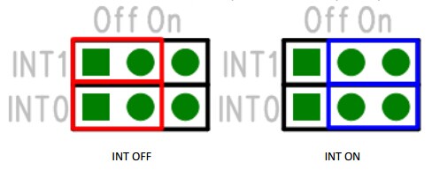
The INT0 is the broke out of the external interrupt pin of GPS module, if not use, please set the jumper to OFF as the following figure. The INT1 is the broke out of the 1PPS output. When the GPS module has tracked to the GPS satellite, this pin will send a pulse per second.
Download
Datasheet for Arduino GPS shield
Schematic for Arduino GPS shield
Useful Links
- ITEAD GPS Shield by powellbob424
- This demo shows use of logging GPS data to an SD Card for later review.
 Notice
