Wboard Pro
Contents
Overview
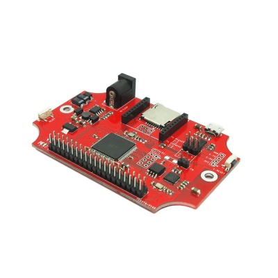
WBoard Pro is a Wifi development board based on Arduino MEGA. With a on-board ESP8266 chip (wifi firmware has been burnt in), you can drive ESP8266 to connect wifi and visit the internet by controlling the serial ports. WBoard Pro supports IoTgo Arduino Library to do a rapid development.
Go shopping Wboard Pro(IM141125005)
Features
- Standard Bee interface, nRF24L01+ interface, SD card slot, PWR/Test indicator
- On-board ESP8266 chip, support wifi connect to internet
- With 40-pin interface that compatiable with Raspberry Pi B+, can use most of the Raspberry Pi add-ons
- Designed to fit an enclosure
Specification
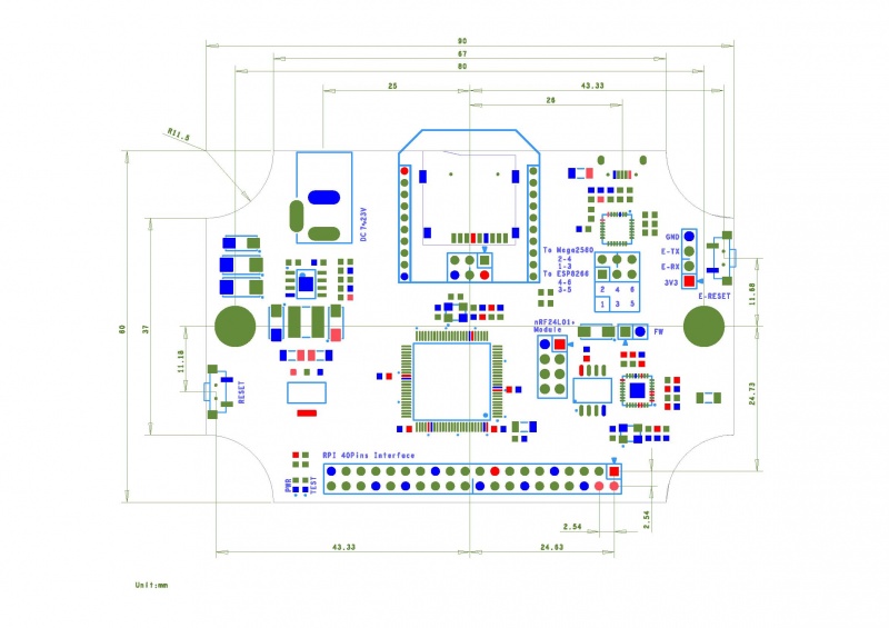
| PCB Size | 90 x 60 x 1.6mm |
| Interface | Standard Bee interface, nRF24L01+ interface, uSD,uUSB |
| Indicator | PWR, Test |
Electrical Characteristics
| Characteristics | Symbol | Min | Typ | Max | Unit |
| Power supply voltage | Vsupply | 7 | - | 23 | V |
| Power for system | VDD | 3.0 | 3.3 | 3.6 | V |
| High input voltage | VIH | 0.8XVDD | - | VDD | V |
| Low input voltage | VIL | 0 | - | 0.2XVDD | V |
| Operation current for VDD | IDD | - | - | 300 | mA |
Hardware
NOTE:
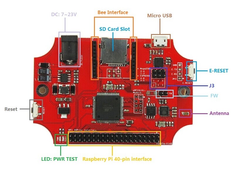
- J3
- When jumpers connect both 2-4 and 1-3, CP2102 will connect to Mega2560’s UART0.
- When jumpers connect both 4-6 and 3-5, CP2102 will connect to ESP8266’s UART0.
- FW
- Connect ESP8266’s GPIO0 to GND. If you want to burn the firmware into ESP8266, you should plug a jumper in FW. After reset ESP8266, you can start to burn the firmware into ESP8266.
- E-RESET
- Hard reset for ESP8266. Besides, ESP8266 RST pin connects to Mega2560 PC0 (Arduino D37). If you set PC0 pin low level, you can make a soft reset on ESP8266.
Pin Map
| Number | name | Mega 2560 pin name | Aduino pin number |
| 1 | 3V3 | ||
| 2 | 5V | ||
| 3 | IIC-SDA | PD0 | D20 |
| 4 | 5V | ||
| 5 | IIC-SCL | PD1 | D21 |
| 6 | GND | ||
| 7 | GPIO0 | PF0 | A0 |
| 8 | TXD2 | PH1 | D16 |
| 9 | GND | ||
| 10 | RXD2 | PH0 | D17 |
| 11 | GPIO1 | PF1 | A1 |
| 12 | GPIO2 | PF2 | A2 |
| 13 | GPIO3 | PF3 | A3 |
| 14 | GND | ||
| 15 | GPIO4 | PF4 | A4 |
| 16 | GPIO5 | PF5 | A5 |
| 17 | 3V3 | ||
| 18 | GPIO6 | PF6 | A6 |
| 19 | SPI-MOSI | PB2 | D51 |
| 20 | GND | ||
| 21 | SPI-MISO | PB3 | D50 |
| 22 | CS | PG1 | D40 |
| 23 | SPI-SCK | PB1 | D52 |
| 24 | SPI-NSS | PB0 | D53 |
| 25 | GND | ||
| 26 | GPIO7 | PF7 | A7 |
| 27 | GPIO8 | PK0 | A8 |
| 28 | GPIO9 | PK1 | A9 |
| 29 | GPIO10 | PK2 | A10 |
| 30 | GND | ||
| 31 | GPIO11 | PK3 | A11 |
| 32 | GPIO12 | PK4 | A12 |
| 33 | GPIO13 | PK5 | A13 |
| 34 | GND | ||
| 35 | GPIO14 | PK6 | A14 |
| 36 | GPIO15 | PK7 | A15 |
| 37 | RST | PG0 | D41 |
| 38 | WR | PG2 | D39 |
| 39 | GND | ||
| 40 | RS | PD7 | D38 |
Instruction
Reference: AT Commands: http://wiki.iteadstudio.com/ESP8266_Serial_WIFI_Module
Download
Schematic--File:IM141125005-WBoardPro-1.0-Schematic.pdf
Useful links
Firmware Update Tutorial: https://www.itead.cc/blog/esp8266-firmware-update-general-tutorial
 Notice

