IR Shield
From ITEAD Wiki
Contents
Overview
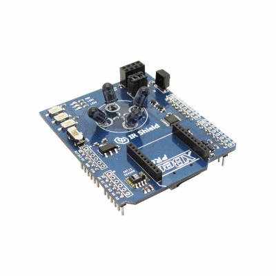
IR Shield is designed for Arduino, which is equipped with infrared receiving and dispatching module, nRF24L01 interface, Xbee interface, Micro SD slot and temperature and humidity sensor. With this IR shield, you can intelligentize your home by making a DIY monitor for indoor temperature and humidity or a controller for IR home appliances such as air-condition and television.
Go shopping
Features
- Compatible for 5/3.3V main board
- Micro SD card slot
- Xbee interface
Specification
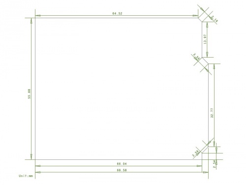
| PCB size | 55.88mm X 68.58mm X 1.6mm |
| Power supply | 5V DC |
| Indicators | PWR,LED1,LED2 |
| Communication Protocol | UART,IIC,SPI |
Electrical Characteristics
| Parameter | Min. | Typical | Max. | Unit |
| Power voltage | 4.5 | 5 | 5.5 | VDC |
| Input voltage VinH (Target Voltage = 3.3V) | 3 | 3.3 | 3.6 | V |
| Input voltage VinH (Target Voltage = 5V) | 4.5 | 5 | 5.5 | V |
| Input voltage VinL | -0.3 | 0 | 0.5 | V |
| Current Consumption | - | 40 | - | mA |
Hardware
Pin Map
| Arduino Pin | Description |
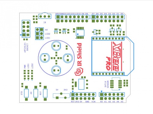
| D0 | XBEE_TX |
| D1 | XBEE_RX |
| D2 | nRF24L01_IRQ & STD Button |
| D3 | IR_TX* |
| D4 | SD_CS |
| D5 | IR_RX* |
| D6 | LED1* |
| D7 | LED2* |
| D8 | - |
| D9 | nRF24L01_CE |
| D10 | nRF24L01_CS |
| D11 | MOSI |
| D12 | MISO |
| D13 | SCK |
| A0 | A0 Button |
| A1 | - |
| A2 | - |
| A3 | - |
| A4 | SHT10_SDA |
| A5 | SHT10_SCL |
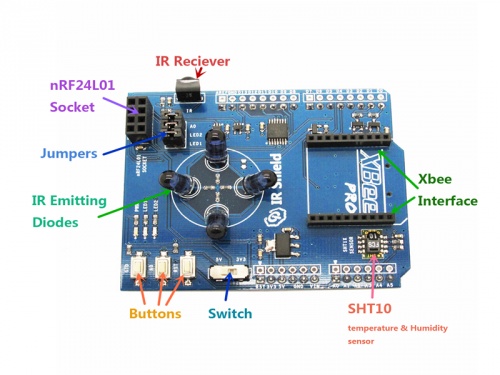
- IR_TX: when D3 is set as high level switch, IR Diode will emit signals out. When D3 is set as low level switch, IR Diode won’t work.
- IR_RX: Use HS0038B as IR receiving module
- Jumpers:
- Jumpers can directly connect to Arduino’s IO. If you don’t need them or their corresponding pins are occupied, you can remove the jumpers.
- A0: insert a 10K resistance to A0 button
- LED1: connect to D6 pin. If the output voltage is high, LED1 turns on.
- LED2: connect to D7 pin. If the output voltage is high, LED1 turns on.
- Switch: Set the switch level according to Arduino main board. When the mainboard is set in 5V, you should turn the switch to 5V; when in 3.3V, you should turn to 3.3V.
Instruction
Please refer to our blogs:
Download
- Schematic--File:IM140715001-IR Shield-schematic.pdf
- IR Receiver Datasheet--File:IM140715001-HS0038B.pdf
- SHT1x Datasheet--File:SHT1x_Datasheet.pdf
 Notice


