433Mhz RF receiver
From ITEAD Wiki
Contents
Overview
433Mhz RF receiver module is a low power consumption, high sensitivity radio receiver module. It uses internal software decoding and comes with data decoding circuit, no additional circuit needed to realize signal input and data output. Developers can simply develop wireless communication function through this module.
Go shopping RF receiver-433Mhz (SKU:IM160127001)
Features
- Input voltage range: 3.3V~5.0V
- Low power consumption: 5V @433.92M, 3.8mA~6mA
- Working frequency: 433.92M(can customize to 315M,390M,418M, etc.)
- Modulation: ASK
- Output mode: L mode(input valid signal , output corresponding signal. Valid signal disappear, it auto stop output)
- Support multiple controller, such as controller with chip PT2260,PT2262,PT2264,EV1527, etc.
- Good local oscillator radiation suppression, no interfering when single transmit and multiple receive
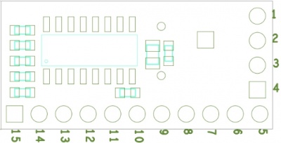
Pinmap
| Pin Index | Pin Name | Description |
| 1 | NC | NC |
| 2 | NC | NC |
| 3 | NC | NC |
| 4 | NC | NC |
| 5 | GND | GND |
| 6 | VDD | Power High(3.0V~5.5V) |
| 7 | D3 | Data output (high default, active LOW) |
| 8 | D2 | Data output (high default, active LOW) |
| 9 | D1 | Data output (high default, active LOW) |
| 10 | D0 | Data output (high default, active LOW) |
| 11 | NC | NC |
| 12 | SW | Button pin, active LOW |
| 13 | LED | Led pin, active high |
| 14 | GND | GND |
| 15 | ANT | Antenna Pin |
Usage
- Pairing: press SW button for 2s, indicator led turns on to enter into pairing mode; release the button, indicator led turns off. Press one of the buttons on RF remote(one button every time), indicator led flashes 4 times every 300ms, which means paired successfully, saved value of the button and exited pairing mode.
- Output: press a successfully paired button to receive valid data, indicator led will be on for 200ms, data port (corresponding one in D0~D3) will turn off for 200ms.
- Clear: press SW for 8s, indicator led will be on at 2s and off at 8s. All pairing codes will be cleared, all buttons will be invalid.
Download
File:433Mhz RF receiver module V1.0.0- schematic.pdf
 Notice
