SIM808 GSM/GPRS/GPS Module
Contents
Overview
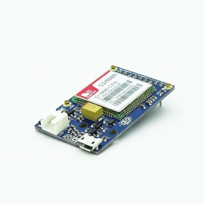
SIM808 module is a GSM and GPS two-in-one function module. It is based on the latest GSM/GPS module SIM808 from SIMCOM, supports GSM/GPRS Quad-Band network and combines GPS technology for satellite navigation.
It features ultra-low power consumption in sleep mode and integrated with charging circuit for Li-Ion batteries, that make it get a super long standby time and convenient for projects that use rechargeable Li-Ion battery. It has high GPS receive sensitivity with 22 tracking and 66 acquisition receiver channels. Besides, it also supports A-GPS that available for indoor localization.
The module is controlled by AT command via UART and supports 3.3V and 5V logical level.
Go shopping SIM808 GSM/GPRS/GPS Module(IM141125004)
Specification
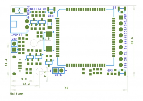
| PCB size | 50mm X 30.5mm X 1.6mm |
| Voltage Input | 3.4V ~ 4.4V |
| Interface | UART |
| Indicator | NET, STATUS |
| Button | POWER |
Features
- Quad-band 850/900/1800/1900MHz
- GPRS multi-slot class12 connectivity: max. 85.6kbps(down-load/up-load)
- GPRS mobile station class B
- Controlled by AT Command (3GPP TS 27.007, 27.005 and SIMCOM enhanced AT Commands)
- Supports charging control for Li-Ion battery
- Supports Real Time Clock
- Supply voltage range 3.4V ~ 4.4V
- Integrated GPS/CNSS and supports A-GPS
- Supports 3.0V to 5.0V logic level
- Low power consumption, 1mA in sleep mode
- Supports GPS NMEA protocol
- Standard SIM Card
Electronic Characteristics
| ' | Min | Typical | Max | Unit |
| Voltage Input(VBAT) | 3.4 | - | 4.4 | VDC |
| Input voltage VinH(Target Voltage = 3.3V ) | 3 | 3.3 | 3.6 | V |
| Input voltage VinH(Target Voltage = 5V ) | 4.5 | 5 | 5.5 | V |
| Input voltage VinL | -0.3 | 0 | 0.5 | V |
| Peak Current | 0 | - | 2 | A |
| Average Current | 2 | - | 500 | mA |
Hardware
Interface Functions
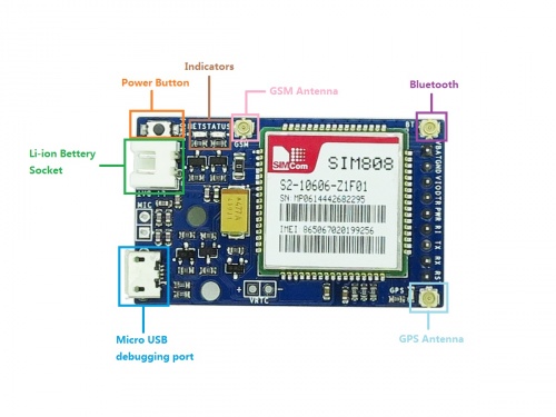
- GPS Antenna: this is an uFL GPS antenna connector. You can connect either passive or active GPS antenna to it. Active GPS antenna runs at 2.8V voltage.
- MicroUSB: the charging interface for Li-Ion battery, of input voltage range from 5V to 7V. Beside, it is also the software debugging interface for SIM808 that you can upgrade firmware and debug software.
- Power Button: this is the hard power switch for the module. When the module is power up, you can turn on or turn off the module by pressing the button for 2s.
- Net Indicator: Red LED, it will tell the what status is about the module linking to network.
- Status Indicator: Green LED, it will tell whether the module is on, light when the module is running.
- Li-ion Battery: this is power supply for the module, input voltage is from 3.4V to 4.4V. It uses the XH-2.0mm connector, that make it convenient to connect to 3.7V Li-Po Battery.
- GSM Antenna: this is an uFL GSM antenna connector, just connect it to a GSM antenna for receiving GSM signal.
- SIM - Card Holder: SIM card holder for standard SIM card
- Microphone: this is the reserved interface for 2.8V microphone. By using the microphone, you can make voice calls and collect speech data around the module.
- VRTC: RTC backup. You can add external capacitor or rechargeable battery on it.
Pin Map
- PWR: this is soft power switch for the module, you can pull it to high level for at least 2s to power up or power down the module.
- RI: this pin will tell you whether the module is on and is there any calls and messages received. It will be pulled to high level when the module is on. And it will change to low for 120ms when a call or message is received.
- RST: this is reset pin for the module. By default it has a high pull-up. If you absolutely got the module in a bad space, you can pull it to low level for 100ms to perform a hard reset.
- RXD / TXD: Serial port, the module uses it to send and receive commands and data. TXD is output, and RXD is input. They can be connected to the 3.3V and 5V level.
- VIO: this is the reference logic level for serial port of the module, the input voltage depends on the logical level of the miccontroller you use. If you use a 5V miccontroller like Arduino, you should have it be 5V, and a 3V logic miccontroller you should set it to 3V.
- BAT: this pin is connected to Li-Ion battery pin, if you want to use only one Li-Ion battery as your power supply, you can use it to drive you miccontroller.
- DTR: this is wake up pin for module in sleep mode. By default it has a high pull-up, and you can set the module into sleep mode by AT command “AT+CSCLK=1”. In the meantime, the serial port will be disabled. To wake up the module and enable serial port, you can pull this pin to low level for about 50ms.
LED Statu
| LED | Status | Function |
| Status Indicator (Green) | Off | Power of LoNet is off |
| On | Power of LoNet is on | |
| Net Indicator (Red) | Off | Power of LoNet is off |
| 64ms on/800ms off | Module can't find the network | |
| 64ms On/3000ms Off | Module has connected to network | |
| 64ms ON/3000ms Off | GPRS communication |
Useful Link
- library:
https://github.com/MarcoMartines/GSM-GPRS-GPS-Shield
 Notice

