ESP8266 Serial WIFI Module
Contents
Overview
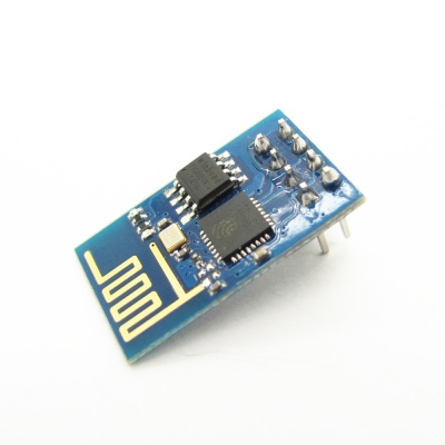
ESP8266 offers a complete and self-contained Wi-Fi networking solution, allowing it to either host the application or to offload all Wi-Fi networking functions from another application processor.When ESP8266 hosts the application, and when it is the only application processor in the device, it is able to boot up directly from an external flash. It has integrated cache to improve the performance of the system in such applications, and to minimize the memory requirements.
Alternately, serving as a Wi-Fi adapter, wireless internet access can be added to any microcontroller-based design with simple connectivity through UART interface or the CPU AHB bridge interface.
ESP8266 on-board processing and storage capabilities allow it to be integrated with the sensors and other application specific devices through its GPIOs with minimal development up-front and minimal loading during runtime. With its high degree of on-chip integration, which includes the antenna switch balun, power management converters, it requires minimal external circuitry, and the entire solution, including front-end module, is designed to occupy minimal PCB area.
Sophisticated system-level features include fast sleep/wake context switching for energy-efficient VoIP, adaptive radio biasing for low-power operation, advance signal processing, and spur cancellation and radio co-existence features for common cellular, Bluetooth, DDR, LVDS, LCD interference mitigation.
Go shopping ESP8266 Serial WIFI Module(IM140905002)
Features
- 802.11 b/g/n protocol
- Wi-Fi Direct (P2P), soft-AP
- Integrated TCP/IP protocol stack
- Integrated TR switch, balun, LNA, power amplifier and matching network
- Integrated PLL, regulators, and power management units
- +19.5dBm output power in 802.11b mode
- Integrated temperature sensor
- Supports antenna diversity
- Power down leakage current of < 10uA
- Integrated low power 32-bit CPU could be used as application processor
- SDIO 2.0, SPI, UART
- STBC, 1×1 MIMO, 2×1 MIMO
- A-MPDU & A-MSDU aggregation & 0.4s guard interval
- Wake up and transmit packets in < 2ms
- Standby power consumption of < 1.0mW (DTIM3)
Electronic Characteristics
1.Current Consumption
The following current consumption is based on 3.3V supply, and 25℃ ambient, using internal regulators. Measurements are done at antenna port without SAW filter. All the transmitter’s measurements are based on 90% duty cycle, continuous transmit mode.
| Mode | Min | Typ | Max | Unit |
| Transmit 802.11b, CCK 1Mbps, POUT=+19.5dBm | 215 | mA | ||
| Transmit 802.11b, CCK 11Mbps, POUT=+18.5dBm | 197 | mA | ||
| Transmit 802.11g, OFDM 54Mbps, POUT =+16dBm | 145 | mA | ||
| Transmit 802.11n, MCS7, POUT=+14dBm | 135 | mA | ||
| Receive 802.11b, packet length=1024 byte, -80dBm | 60 | mA | ||
| Receive 802.11g, packet length=1024 byte, -70dBm | 60 | mA | ||
| Receive 802.11n, packet length=1024 byte, -65dBm | 62 | mA | ||
| Standby | 0.9 | mA | ||
| Deep sleep | 10 | uA | ||
| Power save mode DTIM 1 | 1.2 | mA | ||
| Power save mode DTIM 3 | 0.86 | mA | ||
| Total shutdown | 0.5 | uA |
2.RF Performance
The following are measured under room temperature conditions with 3.3V and 1.1V power supplies.
| Description | Min | Typical | Max | Unit |
| Input frequency | 2412 | 2484 | MHz | |
| Input impedance | 50 | Ω | ||
| Input reflection | -10 | dB | ||
| Output power of PA for 72.2Mbps | 14 | 15 | 16 | dBm |
| Output power of PA for 11b mode | 17.5 | 18.5 | 19.5 | dBm |
| Sensitivity | ||||
| CCK, 1Mbps | -98 | dBm | ||
| CCK, 11Mbps | -91 | dBm | ||
| 6Mbps (1/2 BPSK) | -93 | dBm | ||
| 54Mbps (3/4 64-QAM) | -75 | dBm | ||
| HT20, MCS7 (65Mbps, 72.2Mbps) | -71 | dBm |
Hardware
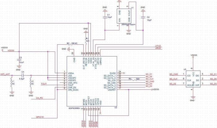
Schematic
Application Notes
- Smart power plugs
- Home automation
- Mesh network
- Industrial wireless control
- Baby monitors
- IP Cameras
- Sensor networks
- Wearable electronics
- Wi-Fi location-aware devices
- Security ID tags
- Wi-Fi position system beacons
AT Commands
Format
- Baud rate at 57600
- x is the commands
| Set | Inquiry | Test | Execute |
|---|---|---|---|
| AT+<x>=<…> | AT+<x>? | AT+<x>=? | AT+<x> |
| AT+CWMODE=<mode> | AT+CWMODE? | AT+CWMODE=? | - |
| Set the network mode | Check current mode | Return which modes supported | - |
Commands
- carefully there are must be no any spaces between the " and IP address or port
|
Commands |
Description |
Type |
Set/Execute |
Inquiry |
test |
Parameters and Examples |
|---|---|---|---|---|---|---|
|
AT |
general test |
basic |
- |
- |
- |
- |
|
AT+RST |
restart the module |
basic |
- |
- |
- |
- |
|
AT+GMR |
check firmware version |
basic |
- |
- |
- |
- |
|
AT+CWMODE |
wifi mode |
wifi |
AT+CWMODE=<mode> |
AT+CWMODE? |
AT+CWMODE=? |
1= Sta, 2= AP, 3=both, Sta is the default mode of router, AP is a normal mode for devices |
|
AT+CWJAP |
join the AP |
wifi |
AT+ CWJAP =<ssid>,< pwd > |
AT+ CWJAP? |
- |
ssid = ssid, pwd = wifi password |
|
AT+CWLAP |
list the AP |
wifi |
AT+CWLAP |
|||
|
AT+CWQAP |
quit the AP |
wifi |
AT+CWQAP |
- |
AT+CWQAP=? |
|
|
AT+ CWSAP |
set the parameters of AP |
wifi |
AT+ CWSAP= <ssid>,<pwd>,<chl>, <ecn> |
AT+ CWSAP? |
ssid, pwd, chl = channel, ecn = encryption; eg. Connect to your router: AT+CWJAP="www.electrodragon.com","helloworld"; and check if connected: AT+CWJAP? |
|
|
AT+CWLIF |
check join devices' IP |
wifi |
AT+CWLIF |
- |
- |
|
|
AT+ CIPSTATUS |
get the connection status |
TCP/IP |
AT+ CIPSTATUS |
<id>,<type>,<addr>,<port>,<tetype>= client or server mode |
||
|
AT+CIPSTART |
set up TCP or UDP connection |
TCP/IP |
1)single connection (+CIPMUX=0) AT+CIPSTART= <type>,<addr>,<port>; 2) multiple connection (+CIPMUX=1) AT+CIPSTART= <id><type>,<addr>, <port> |
- |
AT+CIPSTART=? |
id = 0-4, type = TCP/UDP, addr = IP address, port= port; eg. Connect to another TCP server, set multiple connection first: AT+CIPMUX=1; connect: AT+CIPSTART=4,"TCP","X1.X2.X3.X4",9999 |
|
AT+CIPMODE |
set data transmission mode |
TCP/IP |
AT+CIPMODE=<mode> |
AT+CIPSEND? |
0 not data mode, 1 data mode; return "Link is builded" |
|
|
AT+CIPSEND |
send data |
TCP/IP |
1)single connection(+CIPMUX=0) AT+CIPSEND=<length>; 2) multiple connection (+CIPMUX=1) AT+CIPSEND= <id>,<length> |
AT+CIPSEND=? |
eg. send data: AT+CIPSEND=4,15 and then enter the data. |
|
|
AT+CIPCLOSE |
close TCP or UDP connection |
TCP/IP |
AT+CIPCLOSE=<id> or AT+CIPCLOSE |
AT+CIPCLOSE=? |
||
|
AT+CIFSR |
Get IP address |
TCP/IP |
AT+CIFSR |
AT+ CIFSR=? |
||
|
AT+ CIPMUX |
set mutiple connection |
TCP/IP |
AT+ CIPMUX=<mode> |
AT+ CIPMUX? |
0 for single connection 1 for multiple connection |
|
|
AT+ CIPSERVER |
set as server |
TCP/IP |
AT+ CIPSERVER= <mode>[,<port> ] |
mode 0 to close server mode, mode 1 to open; port = port; eg. turn on as a TCP server: AT+CIPSERVER=1,8888, check the self server IP address: AT+CIFSR=? |
||
|
AT+ CIPSTO |
Set the server timeout |
AT+CIPSTO=<time> |
AT+CIPSTO? |
<time>0~28800 in second |
||
|
+IPD |
received data |
For Single Connection mode(CIPMUX=0): + IPD, <len>: |
Download
- File:ESP8266_Specifications_English.pdf
- File:ESP8266 Specifications(Chinese).pdf
- File:ESP8266_AT_Commands_Chinese.pdf
Instruction
Upgrading ESP8266 Firmware
We provide a ESP8266 firmware upgrading tools here. Please download and install it in your computer. You should pay attention that this software is chinese version and it only runs on Windows environment.
File:ESP8266Flasher-x86-v0.9.2.3.zip
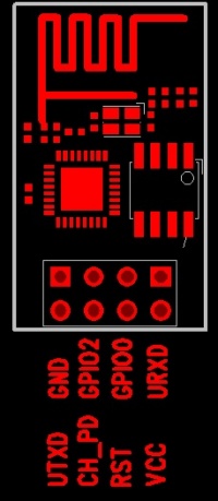
1. Connect your ESP8266 module as follows:
- Vcc = 3.3V (needs around 300-400mA peak)
- Gnd = -ve ground
- CH_PD = Chip enable so always +ve
- RST = Leave floating or ground to reset
- GPIO0 = Normally floating but this needs to be grounded when you start the update.
- UTXD = Tx data connect to Txd on FTDI/Serial interface
- URXD = Rx data connect to Rx of FTDI/Serial interface
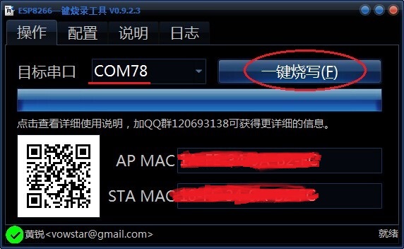
2. Open the software, choose the right COM and click the button that is circled in the following picture. When a tick appears in the bottom-left corner, it suggests that the firmware upgrade successfully.
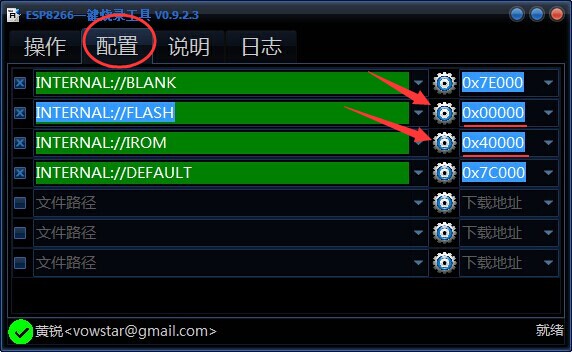
3. This software contains an existing firmware, but if you want to upgrade other ESP8266 firmware, please click the button that is circled in the following picture, and only two file paths are available to choose.
Other ways of ESP8266 firmware upgrading
Useful Link
Reference:
Example of Using it
- http://www.instructables.com/id/Using-the-ESP8266-module/
- The ESP8266 Becomes a Terrible Browser - http://hackaday.io/project/3072/instructions
- New Working GCC for ESP8266 - http://www.esp8266.com/viewtopic.php?f=9&t=224
- http://blog.iteadstudio.com/esp8266-use-android-phone-to-control-itead-rboard/
- SDK for ESP8266 - http://hackaday.com/2014/10/25/an-sdk-for-the-esp8266-wifi-chip/
- An ESP8266 Based Smartmeter - http://hackaday.com/2014/10/25/an-sdk-for-the-esp8266-wifi-chip/
Demos for ESP8266
 Notice