Gboard Pro 800
Contents
Overview
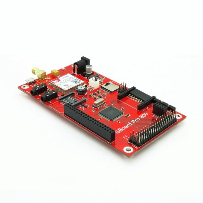
Gboard Pro 800 is a unique Arduino mainboard with SIM800 GSM / GPRS module, XBee socket, nRF24L01 + module interface, micro SD card interface, ITDB02 parallel LCD module interface, electronic brick interface and ATmega2560 chips, which can achieve wireless control via XBee, nRF24L01 + or GSM / GPRS with functions covering from smart home to remote control of robots to meet various needs of different projects.
Note:
- 1. There is a USB connector on the board for debugging or firmware uploading to SIM800 module only.
- 2. The serial interface (bootloader connection) is 3.3v, not the typical 5v as on many Arduino boards - anyone using an alternative to the Foca board must take note not to risk damage.
Go shopping Gboard Pro 800
Features
- SIM800 is a quad-band GSM/GPRS module that works on frequencies GSM 850MHz, EGSM 900MHz, DCS 1800MHz and PCS 1900MHz.
- SIM800 GPRS multi-slot class 12/ class 10 (optional) and supports the GPRS coding schemes CS-1, CS-2, CS-3 and CS-4.
- One USB port can be used as SIM800 debugging and firmware upgrading
- Support Bluetooth function
- Support XBee and nRF24L01+ wireless control
- Require FTDI basic board to upload sketch
- Support various sensor bricks accessing
- Support ITDB02 series TFT modules accessing
Specifications
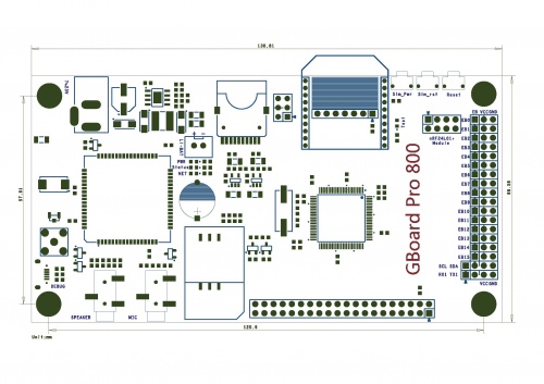
| PCB size | 131.0mm X 68.8mm X 1.6mm |
| Supply voltage | 7~23V DC |
| Operating voltage | 3.3V DC |
| Microprocessor | ATmega2560 |
| Indicators | PWR,NET,Status,Test |
| Communication interfaces | XBee,nRF24L01+,UART,IIC,ITDB02 LCD,micro SD |
Electrical Characteristics
| Parameter | Min. | Typical | Max. | Unit |
| Supply voltage | 7 | - | 23 | VDC |
| Input high voltage VH | 3 | 3.3 | 3.6 | V |
| Input low voltage | -0.3 | 0 | 0.5 | V |
| Average Current consumption | - | 100 | 500 | mA |
| Peak Current consumption | - | - | 2 | A |
Hardware
Note:
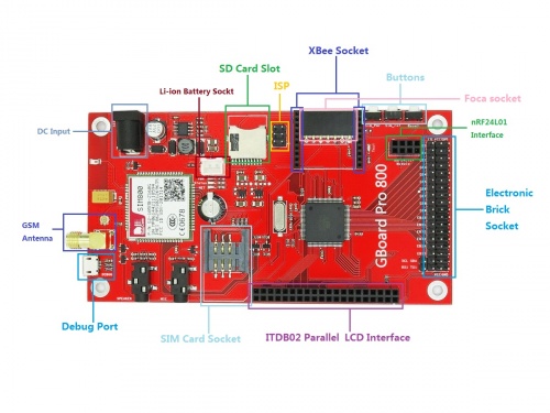
- Baterry Socket: you can connect a Li-ion battery onto the socket to power the board up instead of DC external power supply, the input voltage is from 3.4V~4.4V.
- Debug Port: debugging interface for SIM800 that you can upgrade firmware and debug software.
Indicators
1.PWR
- Power indicator:Normally ON indicates normal power supply to Gboard Pro.
2.Status
- Status indicator:Normally ON indicates SIM800 already powered on.
3.NET
- Network indicator:OFF indicates SIM800 does not work; ON for 64ms / OFF for 800ms indicates SIM800 did not find the network; ON for 64ms / OFF for 3000ms indicates SIM800 registered on the network; ON for 64ms / OFF for 300ms indicates GPRS communication.
Buttons
1.Reset
- ATmega2560 reset button:press the button to reset ATmega2560。
2.Sim_rst
- SIM800 reset button:press the button to reset SIM800。
3.Sim_pwr
- SIM800 power button: if SIM800 is powered off, it will be powered on by keeping pressing the button (for more than 1s); if SIM800 is powered on, it will be powered off by keeping pressing the button (for more than 1s).
Pinmap
- ITDB02 Parallel LCD Module Interface
| Index of Interface | Name of Interface | Index of Arduino | Pin of Atmega2560 |
| 1 | GND | - | - |
| 2 | DB0 | D37 | PC0 |
| 3 | 5V | - | - |
| 4 | DB1 | D36 | PC1 |
| 5 | NC | - | - |
| 6 | DB2 | D35 | PC2 |
| 7 | LCD_RS | D38 | PD7 |
| 8 | DB3 | D34 | PC3 |
| 9 | LCD_WR | D39 | PG2 |
| 10 | DB4 | D33 | PC4 |
| 11 | LCD_RD | 3V3 | 3V3 |
| 12 | DB5 | D32 | PC5 |
| 13 | DB8 | D22 | PA0 |
| 14 | DB6 | D31 | PC6 |
| 15 | DB9 | D23 | PA1 |
| 16 | DB7 | D30 | PC7 |
| 17 | DB10 | D24 | PA2 |
| 18 | Touch_CLK | D6 | PH3 |
| 19 | DB11 | D25 | PA3 |
| 20 | Touch_CS | D5 | PE3 |
| 21 | DB12 | D26 | PA4 |
| 22 | Touch_DIN | D48 | PL1 |
| 23 | DB13 | D27 | PA5 |
| 24 | Touch_BUSY | - | - |
| 25 | DB14 | D28 | PA6 |
| 26 | Touch_DOUT | D3 | PE5 |
| 27 | DB15 | D29 | PA7 |
| 28 | Touch_IRQ | D2 | PE4 |
| 29 | LCD_CS | D40 | PG1 |
| 30 | SD_MISO | D50 | PB3 |
| 31 | NC | - | - |
| 32 | SD_SCK | D52 | PB1 |
| 33 | LCD_RST | D41 | PG0 |
| 34 | SD_MOSI | D51 | PB2 |
| 35 | NC | - | - |
| 36 | SD_CS | D53 | PB0 |
| 37 | LED+ | 3V3 | 3V3 |
| 38 | NC | - | - |
| 39 | LED- | GND | GND |
| 40 | NC | - | - |
- Electronic Bricks Interface
| Index of Interface | Name of Interface | Index of Arduino | Pin of Atmega2560 |
| 1 | EB0 | A0 | PF0 |
| 2 | EB1 | A1 | PF1 |
| 3 | EB2 | A2 | PF2 |
| 4 | EB3 | A3 | PF3 |
| 5 | EB4 | A4 | PF4 |
| 6 | EB5 | A5 | PF5 |
| 7 | EB6 | A6 | PF6 |
| 8 | EB7 | A7 | PF7 |
| 9 | EB8 | A8 | PK0 |
| 10 | EB9 | A9 | PK1 |
| 11 | EB10 | A10 | PK2 |
| 12 | EB11 | A11 | PK3 |
| 13 | EB12 | A12 | PK4 |
| 14 | EB13 | A13 | PK5 |
| 15 | EB14 | A14 | PK6 |
| 16 | EB15 | A15 | PK7 |
| 17 | SCL | D21 | PD0 |
| 18 | SDA | D20 | PD1 |
| 19 | RX1 | D19 | PD2 |
| 20 | TX1 | D18 | PD3 |
- XBee Interface
| Index of Interface | Name of Interface | Index of Arduino | Pin of Atmega2560 |
| 1 | XBee_DOUT | D15(RX3) | PJ0 |
| 2 | XBee_DIN | D14(TX3) | PJ1 |
- SIM800 Communication Interface
| Index of Interface | Name of Interface | Index of Arduino | Pin of Atmega2560 |
| 1 | SIM800_TXD | D17(RX2) | PH0 |
| 2 | SIM800_RXD | D16(TX2) | PH1 |
| 3 | SIM800_RST | D47 | PL2 |
| 4 | SIM800_PWR | D46 | PL3 |
Download
- File:IM141125008 - Gboard Pro 800 - schematic.pdf
- File:SIM800 Series_Bluetooth_Application Note_V1.01.pdf
- File:sim800_hardware_design_v1.05.pdf
- File:SIM800_Series_AT_Command_Manual_V1.05.pdf
Tools:
- Firmware(1308B02SIM800M32_BT) for SIM800 with Bluetooth function
- USB Driver for SIM800
- Tool for Uploading firmware to SIM800
 Notice

