IS Shield
Contents
Overview
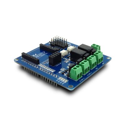
IS Shield with 2 channels mechanical relays and 2 channels MOS switch, providing an easy way for applications of voltage controlling from low to high.
The 3Pins breakout make it easy to build a project or prototyping quickly, by using many existing sensor modules (Electronic Brick). And there are some wireless interface breakout on board, you can use it to connect with many wireless module.
Features
- 2 mechanical relays with photo-coupled circuit
- 2 MOS switch with internal power supply
- Xbee, nRF24l02, RF315/433M module wireless interface
- Arduino AD pins 3 PINs interface breakout for Sensor module (Electronic Brick)
- Equipped with screw holes for easy installation
- Native Arduino/Iteaduino compatibility
Specifications
| PCB size | 67.3mm X 59.1mm X 1.6mm |
| Indicators | PWR, status LED |
| Power supply | 9~20V, compatible with Arduino |
| Communication Protocol | XBee, nRF24L01+,UART, IIC, 315/433 RF module |
| RoSH | Yes |
Electrical Characteristics
| Specification | Min | Type | Max | Unit |
| Power Voltage(Vlogic) | 4.5 | 5 | 5.5 | VDC |
| Power Voltage(Vsupply) | 9 | - | 20 | VDC |
| Input Voltage VH: | 4.5 | 5 | 5.5 | V |
| Input Voltage VL: | -0.3 | 0 | 0.5 | V |
| Current Consumption | - | 400 | mA |
- IS shield just can work with Extenal Power supply or with the Arduino that using Extenal Powe
supply, and it cannot work with Arduino which using USB 5V power supply.
Hardware

Figure 1 Top Map
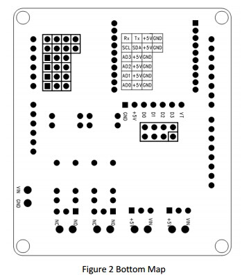
| Interface | Pin | Description |
| UART | 1 | Ground |
| UART | 2 | 5V supply |
| UART | 3 | Tx |
| UART | 4 | Rx |
| AD0/1/2 | 1 | AD0/1/2 |
| AD0/1/3 | 2 | 5V supply |
| AD0/1/4 | 3 | Ground |
| IIC | 1 | Ground |
| IIC | 2 | 5V supply |
| IIC | 3 | Data wire of IIC |
| IIC | 4 | Clock wire of IIC |
| nRF24L01+ Socket | 1 | GND |
| nRF24L01+ Socket | 2 | VCC33 |
| nRF24L01+ Socket | 3 | CE(Chip Enable) |
| nRF24L01+ Socket | 4 | SPI_CS |
| nRF24L01+ Socket | 5 | SPI_SCK |
| nRF24L01+ Socket | 6 | SPI_MOSI |
| nRF24L01+ Socket | 7 | SPI_MISO |
| nRF24L01+ Socket | 8 | nRF24L01+ IRQ Output |
| XBee Socket | 1 | VCC33 |
| XBee Socket | 2 | Dout |
| XBee Socket | 3 | Din |
| XBee Socket | 10 | GNF |
| XBee Socket | 4,5,6,7,8,9,11,12,13,14,15,16,17,18,19,20 | No Connect |
| 315/433MHz RF module socket | 1 | GND |
| 315/433MHz RF module socket | 2 | VCC |
| 315/433MHz RF module socket | 3 | D0 |
| 315/433MHz RF module socket | 4 | D1 |
| 315/433MHz RF module socket | 5 | D2 |
| 315/433MHz RF module socket | 6 | D3 |
| 315/433MHz RF module socket | 7 | VT |
Arduino Socket defination
| Pin | Description |
| D0 | XBee_Dout/UART_Rx |
| D1 | XBee_Din/UART_Tx |
| D2 | nRF24L01+_IRQ |
| D3 | VT |
| D4 | Channel 1 Enable(High active) |
| D5 | Channel 2 Enable(High active) |
| D6 | Channel 3 Enable(High active) |
| D7 | Channel 4 Enable(High active) |
| D8 | No connect |
| D9 | nRF24L01+_CE |
| D10 | nRF24L01+_CS |
| D11 | nRF24L01+_MO |
| D12 | nRF24L01+_MI |
| D13 | nRF24L01+_SCK |
| A0 | AD0 |
| A1 | AD1 |
| A2 | AD2 |
| A3 | AD3 |
| A4 | IIC_SCL |
| A5 | IIC_SDA |
Installation
Relay
Is shield can control two relay at the same time. Every channel can be set for Normal Open (NO)/Normal Connect (NC) by J6/J7 when this channel is active as the figure 3.
MOS Switch
Is shield can control two MOS Switch at the same time. The output voltage of every channel of MOS Switch can be set for +5V/VIN by J8/J24, and every channel can supply 1A current max. The jumper setting is as figure 4.
Note: The current of MOS Switch channel depend on the power supply of IS Shield.
 Notice


