VC0706 UART Camera (Supports JPEG)
Contents
Overview
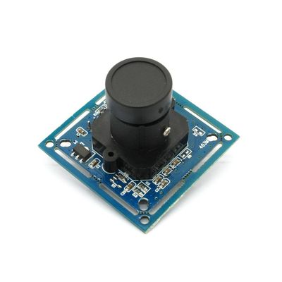
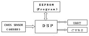
VC0706 UART VGA Camera is an active pixel array of 649H x 489V. It incorporates sophisticated camera functions on-chip such as windowing, column and row mirroring. It is programmable through a simple two-wire serial bus interface and has very low power consumption.
Go shopping VC0706 UART Camera (Supports JPEG) (IM130517001)
Structure
Specification
- Video output:CVBS 30fps
- PCB dimension:38×38mm/32×32mm
- Image sensor:1/4 CMOS image sensor MT9V011
- Image format: PAL, 628×582; NTSC, 510×492; default as NTSC for this module, PAL without resistor R5 (10K), free for users to choose
- Picture format: JPEG
- Image size: VGA / QVGA / QQVGA CIF / QCIF / QQCIF, generally default as QVGA (320*240), users are free to change the * size according to the communication protocol. The smaller the picture, the faster the picture is sent.
- Baud rate: 9600bps-115200bps, default as 38400, users are free to change the rate according to the communication protocol.
- Lens: FOV 60°~120°, 650 ordinary lens / 850, 940 IR lens
- Terminal blocks: 6PIN-2.0mm/2PIN-2.0mm (Infrared light board interface)
- Level: Default as CMOS level, can be modified to TTL level in accordance with the requirements
- Working voltage: DC4.8V ~ DC6.5V
- Working current: 90mA (when infrared light does not work)
- Working temperature: -20℃~ +60℃
- Storage temperature: -30℃~ 70℃
- Humidity: 90% non-condensing
Len Specification
Free to adjust high-speed/ low-speed serial port
- Low-speed serial output: NC for R7,R8,R15 and R16;
- High-speed serial output:NC for R13,R14,R15 and R16;
- Low-speed TTL output:NC for R7,R8 and U7;
- High-speed TTL output:NC for R13,R14 and U7.
Software debugging tool image acquisition process / Command image acquisition process
1. Software tool image acquisition process
First step:
Connect to 5V power supply, then connect the module with computer via serial cable. Please note that the serial port of debugging tool must be the same as the serial port of COM in computer device manager.
If there is no RS232 interface in the laptop , please download a conversion tool to convert USB interface into RS232 interface (this is unstable, not recommended). Please note that the serial port of debugging tool must be the same as the serial port of COM in computer device manager.
Second step:
Open the debugging tool:
Choose correct ‘COM Port BeatRate’(original default as 38400), others remain unchanged, then click ‘Open’.
Click ‘Get Version’,if it indicates ‘successful connection’ in the right, connection succeeds. If it indicates ‘CMD time’, connection fails, please check.
Third step:
Collect images and send them to display on the computer via serial port :
Click ‘Fbuf Ctrl’,a new interface will turn up, then click ‘Stop Fbuf’,click ‘Sel File’ to save the file, finally click ‘Read’ button to read the images.
2. Command image acquisition process:
The following is a continuous operation of photo taking and data uploading for reference only.
Step 1:Send 56 00 36 01 00 to stop current frame
Step 2:Send 56 00 34 01 00 to obtain the data length of current frame
Receive returned data:76 00 34 00 04FF FF FF FF(red indicates bytes of BUFF, 4 bytes)
Step 3:Send:56 00 32 0C 00 0A00 00 00 00FF FF FF FF10 00(blue indicates that the data is with fixed value)
Returned data from the serial port:76 00 32 00 00FF D8 ...Image data... FF D976 00 32 00 00
Step 4:Send :56 00 36 01 03 to recover frame, back to normal working status
Common control commands (for details, please refer to the communication protocol) - Communication guideline
1. Reset command:56 00 26 00 Return:76 00 26 00
2. Photo taking command:56 00 36 01 00 Return:76 00 36 00 00
3. Reading the length of photo taken command:56 00 34 01 00 Return:76 00 34 00 04 00 00 XX YY
XX YY -------Image data length,XX is high byte while YY is low byte
4. Reading data of the photo taken command:56 00 32 0C 00 0A 00 00 XX XX 00 00 YY YY ZZ ZZ
Return:76 00 32 00 00(interval)FF D8.......FF D9(interval)76 00 32 00 00
00 00 XX XX ------starting address (starting address must be multiples of 8, generally set as 00 00)
00 00 YY YY ------image data length(high byte first and then low byte)
ZZ ZZ --------interval(= XX XX*0.01ms,better to set it less, such as 00 0A)
Note:JPEG image file must begin with FF D8 and end up with FF D9
5. Stop photo taking command:56 00 36 01 03 Return:76 00 36 00 00
6. Set photo compression ratio command:56 00 31 05 01 01 12 04 XX Return:76 00 31 00 00
XX is generally selected as 36 (range: 00 ----FF)
7. Set photo size command:
56 00 31 05 04 01 00 19 11 (320*240)Return:76 00 31 00 00
56 00 31 05 04 01 00 19 00 (640*480)
8. Modify serial speed:56 00 24 03 01 XX XX Return:76 00 24 00 00
XX XX Speed
AE C8 9600
56 E4 19200
2A F2 38400
 Notice
