Difference between revisions of "BT Shield (Slave)"
From ITEAD Wiki
(→Electrical Characteristics) |
(→Hardware) |
||
| Line 45: | Line 45: | ||
==Hardware== | ==Hardware== | ||
| + | [[File:BT shield (salve)1.jpg]] | ||
| + | {| class="wikitable" | ||
| + | |- | ||
| + | | align="center" style="background:#f0f0f0;"|'''Pad Name''' | ||
| + | | align="center" style="background:#f0f0f0;"|'''Type''' | ||
| + | | align="center" style="background:#f0f0f0;"|'''Description''' | ||
| + | |- | ||
| + | | RX/TX||I/O||UART communication Port (Depend on switcher 4) | ||
| + | |- | ||
| + | | TX/RX||I/O||UART communication Port (Depend on switcher 4) | ||
| + | |- | ||
| + | | State||O||State Direction | ||
| + | |} | ||
| + | |||
| + | {| class="wikitable" | ||
| + | |- | ||
| + | | align="center" style="background:#f0f0f0;"|'''Switcher''' | ||
| + | | align="center" style="background:#f0f0f0;"|'''Name''' | ||
| + | | align="center" style="background:#f0f0f0;"|'''Description''' | ||
| + | |- | ||
| + | | 4||UART Communication Switch||Connect to broad or FT232 | ||
| + | |- | ||
| + | | 5||Communication Voltage Switch||Set the interface voltage | ||
| + | |} | ||
| + | |||
| + | {| class="wikitable" | ||
| + | |- | ||
| + | | align="center" style="background:#f0f0f0;"|'''LED''' | ||
| + | | align="center" style="background:#f0f0f0;"|'''Name''' | ||
| + | | align="center" style="background:#f0f0f0;"|'''Description''' | ||
| + | |- | ||
| + | | 6||PWR||When power on, the PWR LED light. | ||
| + | |- | ||
| + | | 7||State||\"When the module in standby mode, the State LED will alternating light off. When the serial port open, the State LED light.\" | ||
| + | |} | ||
==AT command== | ==AT command== | ||
Revision as of 05:53, 22 May 2014
Contents
Overview
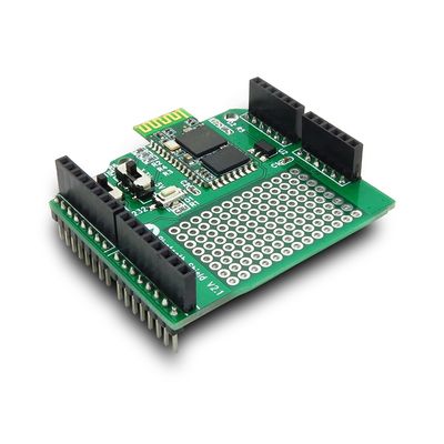
BT Shield V2.1 is a Serial port Bluetooth module (Slave) breakout board, and it’s compatible with Arduino and IFlat-32, it can directly plug in with Arduino/IFlat-32 board, use the UART port for communicating to Arduino/IFlat-32 or FT232.
Specifications
| Microprocessor | CSR BC417 |
| PCB size | 53.3mm X 47mm X 1.6mm |
| Indicators | PWR,State |
| Power supply | 5V DC |
| IO | 3 |
| Communication Protocol | UART/Bluetooth 2.0 |
| RoSH | Yes |
Electrical Characteristics
| Specification | Min | Type | Max | Unit |
| Power Voltage | 4.5 | 5 | 5.5 | VDC |
| Input Voltage VH (Target Voltage = 3.3V) | 3 | 3.3 | 3.6 | VDC |
| Input Voltage VH (Target Voltage = 5V) | 4.5 | 5 | 5.5 | V |
| Input Voltage VL: | -0.3 | 0 | 0.5 | V |
| Current Consumption | - | 20 | 40 | mA |
Hardware
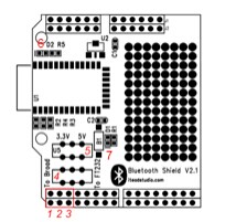
| Pad Name | Type | Description |
| RX/TX | I/O | UART communication Port (Depend on switcher 4) |
| TX/RX | I/O | UART communication Port (Depend on switcher 4) |
| State | O | State Direction |
| Switcher | Name | Description |
| 4 | UART Communication Switch | Connect to broad or FT232 |
| 5 | Communication Voltage Switch | Set the interface voltage |
| LED | Name | Description |
| 6 | PWR | When power on, the PWR LED light. |
| 7 | State | \"When the module in standby mode, the State LED will alternating light off. When the serial port open, the State LED light.\" |
 Notice
