Difference between revisions of "RASPBERRY PI SIM900 GSM/GPRS ADD-ON"
(→Download) |
(→Overview) |
||
| Line 1: | Line 1: | ||
==Overview== | ==Overview== | ||
| + | |||
| + | [[File:RaspberryPIGSM Add-on .jpg|thumb|400px|right]] | ||
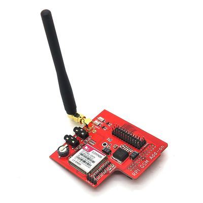
Raspberry PI GSM Add-on is customized for Raspberry Pi interface based on SIM900 quad-band GSM/GPRS module. AT commands can be sent via the serial port on Raspberry Pi, thus functions such as dialing and answering calls, sending and receiving messages and surfing on line can be realized. Moreover, the module supports powering-on and resetting via software. | Raspberry PI GSM Add-on is customized for Raspberry Pi interface based on SIM900 quad-band GSM/GPRS module. AT commands can be sent via the serial port on Raspberry Pi, thus functions such as dialing and answering calls, sending and receiving messages and surfing on line can be realized. Moreover, the module supports powering-on and resetting via software. | ||
Revision as of 07:36, 21 May 2014
Contents
Overview
Raspberry PI GSM Add-on is customized for Raspberry Pi interface based on SIM900 quad-band GSM/GPRS module. AT commands can be sent via the serial port on Raspberry Pi, thus functions such as dialing and answering calls, sending and receiving messages and surfing on line can be realized. Moreover, the module supports powering-on and resetting via software.
Features
- Quad-Band 850/ 900/ 1800/ 1900 MHz
- GPRS multi-slot class 10/8GPRS mobile station class B
- Compliant to GSM phase 2/2+Class 4 (2 W @850/ 900 MHz)
- Class 1 (1 W @ 1800/1900MHz)
- Control via AT commands (GSM 07.07 ,07.05 and SIMCOM enhanced AT Commands)
- Low power consumption: 1.5mA(sleep mode)
- Operation temperature: -40°C to +85 °C
Specifications
| PCB size | 73.8mm X 70mm X 1.6mm |
| Input voltage | 5V |
| Interface | UART |
| Baud rate | 9600 (default) |
Electrical characteristics
| Parameter | Min. | Typical | Max. | Unit |
| Supply voltage | - | 5 | 5.5 | VDC |
| Current consumption (average) | - | 500 | - | mA |
| Instantaneous current consumption | - | - | 2 | A |
Hardware

Pinmap
Raspberry PI interfaces
| Raspberry PI Pin N.O. | Pin name | Pin of SIM900 Module | Description |
| 11 | GPIO0 | SIM900-PWERKEY | Powering-on key via software |
| 12 | GPIO1 | SIM900-RST | Resetting key via software |
| 13 | GPIO2 | - | |
| 15 | GPIO3 | - | |
| 16 | GPIO4 | - | |
| 18 | GPIO5 | - | |
| 22 | GPIO6 | - | |
| 7 | GPIO7 | - | |
| 3 | SDA0 | - | |
| 5 | SCL0 | - | |
| 24 | CE0 | - | |
| 26 | CE1 | - | |
| 19 | MOSI | - | |
| 21 | MISO | - | |
| 23 | SCLK | - | |
| 8 | TXD | SIM900_RX | Receiving end for SIM900 serial port |
| 10 | RXD | SIM900_TX | Sending end for SIM900 serial port |
| 2 | +5V | - | |
| 1 | +3.3V | - | |
| 6 | GND | - |
Other interfaces
| Pin name | Description |
| DR | Receiving end for SIM900 debugging serial port |
| DT | Sending end for SIM900 debugging serial port |
| VBAT | SIM900 supply 4.2V |
| G | Ground |
| V | Electronic brick interface supply pin 3.3V |
Indicators
- PWR
Power: When there is normal supply to the board, the indicator keeps on.
- STATUS
SIM900 status: When SIM900 works normally, the indicator keeps on.
- NET
SIM900 network status: used to indicate network status, the working status of the indicator is as below:
| Network indicator status | SIM900 working status |
| OFF | SIM900 does not work |
| 64ms on/800ms off | SIM900 does not find network |
| 64ms on/3000ms off | SIM900 registers the network |
| 64ms on/300ms off | GPRS communicates |
Keys
- SIM900-PWRKEY
SIM900 powering-on key: Keep pressing the key for more than 1 second, SIM900 will be powered on; keep pressing the key for more than 1 second after the board is powered on, SIM900 will be powered off.
- SIM900-RST
SIM900 resetting key: press the key, SIM900 will be reset.
Note
The module does not support hot swapping.
Download
Datasheet for RASPBERRY PI SIM900 GSM/GPRS ADD-ON
Schematic for RASPBERRY PI SIM900 GSM/GPRS ADD-ON
Library for RASPBERRY PI SIM900 GSM/GPRS ADD-ON
 Notice