Difference between revisions of "SPD8001"
m (→Overview) |
m (→Overview) |
||
| Line 5: | Line 5: | ||
With multiple protecting functions such as over current, input under voltage and over temperature, this module provides a stable and reliable PoE solution for you. | With multiple protecting functions such as over current, input under voltage and over temperature, this module provides a stable and reliable PoE solution for you. | ||
| − | Go shopping [SPD8001(IM141020002)] | + | Go shopping [http://imall.iteadstudio.com/im141020002.html SPD8001(IM141020002)] |
==Features== | ==Features== | ||
Latest revision as of 03:35, 28 October 2014
Contents
Overview
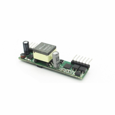
In the PoE scheme, two different types of devices are involved: Power Sourcing Equipment (PSE) and Powered Devices (PD). Compatible with IEEE802.3af standard, SPD8001 is an isolation type PD module for PoE system so that the electric energy can pass from PSE to SPD8001 module though Ethernet cable.
With multiple protecting functions such as over current, input under voltage and over temperature, this module provides a stable and reliable PoE solution for you.
Go shopping SPD8001(IM141020002)
Features
- Compatible with IEEE802.3af standard
- Support 10M/100M/1000M power on Ethernet system
- Support End-point and Mid-span modes
- Support PoE power management from class 0 to class 3
- Under Voltage Protection, Over Temperature Protection, Surge Protection
- Isolation Voltage 1.5KV rms
Application Notes
- NVR
- NAS
- VolP Phone
- IP Camera
- RFID system
- Entrance Surveillance System
- 100M/1000M Ethernet gateway/router
- WiMAX ASN/BTS and CPE/ODU system
Electronic Characteristics
| Test Conditions | Min | Typical | Max | Unit | |
| VPORT_Max | VA1/VA2 pin or VB1/VB2 pin | -60 | +60 | V | |
| VPORT | VA1/VA2 pin or VB1/VB2 pin(ABS) | 36 | 57 | V | |
| VPORT_UVLO | Shut down | 42 | V | ||
|---|---|---|---|---|---|
| Open | 30 | 36 | |||
| IPORT | Class 0 | 0 | &minus | 4 | mA |
| Class 1 | 9 | - | 12 | ||
| Class 2 | 17 | - | 20 | ||
| Class 3 | 26 | - | 30 | ||
| ILIM | Impulse Current | 140 | mA | ||
| Limited Current | 470 | 680 | mA | ||
| ISO_Volt | 1.5 | kVrms | |||
| Tss | 3 | mS | |||
| IOUT | VOUT=12.0V | 1 | A | ||
| VOUT=5.0V | 2 | A | |||
| VOUT=3.3V | 3 | A | |||
| T_OP* | 0 | - | 70 | ℃ | |
| T_stroage | -10 | - | 70 | ℃ | |
| *Note: Customizable for industrial products (-40~85℃) | |||||
Hardware
Pin Map
| Number | Pin | description |
| 1 | VA1 | PoE Mode A Positive Input |
| 2 | VA2 | PoE Mode A Negative Input |
| 3 | VB1 | PoE Mode B Negative Input |
| 4 | VB2 | PoE Mode B Positive Input |
| 5 | CP1 | RCL* |
| 6 | CP2 | RCL* |
| 7 | GND | |
| 8 | VOUT | |
| 9 | VOUT | |
| 10 | GND |
∗Note: CP1/CP2 Resistance Type as below table
| Power Type | In Use | Peak Power | IPORT | RCL(1%,1/16W) |
| 0 | Default | 0.44 to 12.95W | < 4mA | >1.33k |
| 1 | Optional | 0.44 to 3.84W | 10.5mA | 127Ω |
| 2 | Optional | 3.84 to 6.49W | 18.5mA | 69.8Ω |
| 3 | Optional | 6.49 to 12.95W | 28mA | 45.3Ω |
| 4 | POE+ | 12.95 to 17W | 40mA | 30.9Ω |
 Notice
