Difference between revisions of "ITDB02-2.2S"
m (→Instruction) |
m (→Overview) |
||
| Line 2: | Line 2: | ||
[[File:IM140714001_6.jpg|thumb|400px|right]] | [[File:IM140714001_6.jpg|thumb|400px|right]] | ||
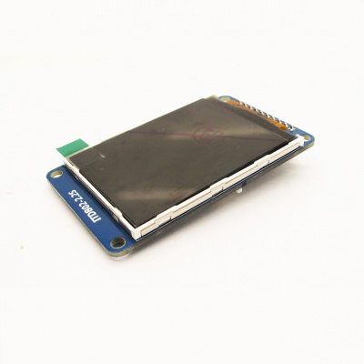
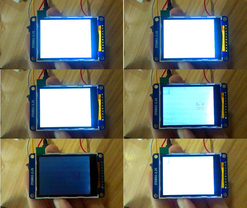
ITDB02-2.2S module is 2.2" SPI TFT LCD with 262K color 320 x 240 resolutions. The controller chip of this LCD module is ILI9341, providing different pin-saving SPI communication without sacrificing the data transmitting speed. Since its interface is SPI, you need 6 Dupont lines (SCK,MISO,MOSI,CS,D/C,RST) to control this LCD module. Moreover, this module integrates an SD card slot. | ITDB02-2.2S module is 2.2" SPI TFT LCD with 262K color 320 x 240 resolutions. The controller chip of this LCD module is ILI9341, providing different pin-saving SPI communication without sacrificing the data transmitting speed. Since its interface is SPI, you need 6 Dupont lines (SCK,MISO,MOSI,CS,D/C,RST) to control this LCD module. Moreover, this module integrates an SD card slot. | ||
| + | |||
| + | Go to shopping [http://imall.iteadstudio.com/im140714001.html ITDB02-2.2S] | ||
==Features== | ==Features== | ||
Revision as of 02:19, 21 July 2014
Contents
Overview
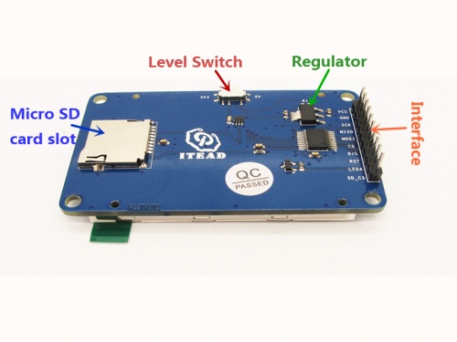
ITDB02-2.2S module is 2.2" SPI TFT LCD with 262K color 320 x 240 resolutions. The controller chip of this LCD module is ILI9341, providing different pin-saving SPI communication without sacrificing the data transmitting speed. Since its interface is SPI, you need 6 Dupont lines (SCK,MISO,MOSI,CS,D/C,RST) to control this LCD module. Moreover, this module integrates an SD card slot.
Go to shopping ITDB02-2.2S
Features
- Compatible to 3.3/5V operating level
- Integrated with an micro SD card slot
- Support IO/PMW to control the backlight
Specifications
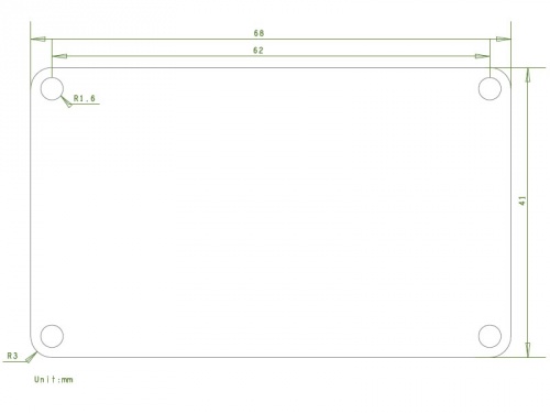
| PCB size | 41mm X 68mm X 1.6mm |
| Power supply | 5V DC |
| Driver IC | ILI9341 |
| Resolution | 320*240 |
| LED numbers | 4LEDs |
Electrical Characteristics
| Parameter | Min. | Typical | Max. | Unit |
| Power voltage | 4.5 | 5 | 5.5 | VDC |
| Input voltage VinH (Target Voltage = 3.3V) | 3 | 3.3 | 3.6 | V |
| Input voltage VinH (Target Voltage = 5V) | 4.5 | 5 | 5.5 | V |
| Input voltage VinL | -0.3 | 0 | 0.5 | V |
| Current Consumption | - | 40 | 80 | mA |
Hardware
Pin Map
| Pin | Type* | Description |
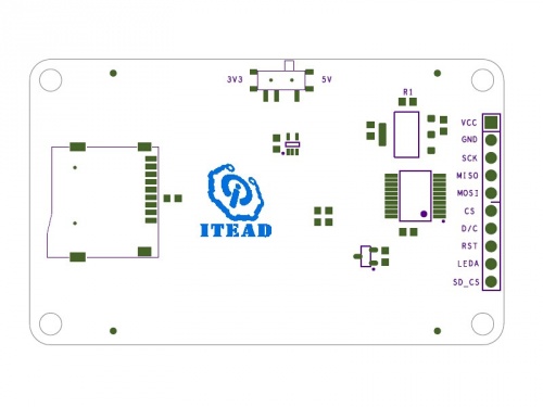
| VCC | P | 5V Power supply pin |
| GND | G | Ground |
| SCK | I | SPI SCK |
| MISO | O | SPI MISO |
| MOSI | I | SPI MOSI |
| CS | I | Chip Select for TFT |
| D/C | I | Command or parameter select |
| RST | I | RESET signal for TFT |
| LEDA* | I | Backlight control pin |
| SD_CS | I | Chip Select for SD |
- Type: P--Power supply; G--Ground; I--Input; O--Output.
- LEDA: When LEDA is set as high electronic level, the backlight turns on. When it's set as low electronic level, the backlight turns off.
Instruction
Display the image from micro SD card
- download the library from this link: https://github.com/adafruit/Adafruit_ILI9340 , then extract it into the directory \arduino\libraries
- copy the image woof.bmp from the directory Adafruit_ILI9340\examples\spitftbitmap to your SD card, then plug the card into the SD card slot on ITDB02-2.2S LCD module
- Use arduino IDE to open spitftbitmap.ino in the directory Adafruit_ILI9340\examples\spitftbitmap then upload it to UNO main board. Select 5V electronic level in the 2.2S LCD module, then use dupont lines to connect UNO and LCD module according to the table as below:
| 2.2S pins | UNO pins |
| VCC | 5V |
| GND | GND |
| SCK | D13 |
| MISO | D12 |
| MOSI | D11 |
| CS | D10 |
| D/C | D9 |
| RST | D8 |
| LEDA | 5V/3V3 |
| SD_CS | D4 |
- Power UNO main board, a picture of dog showed on the display.
Control LEDA backlight via PWM pins
- Use arduino IDE to open the demo 0.1Basics\Fade, then upload it into UNO
- Connect ITDB02-2.2S module to UNO according to the table as below:
| 2.2S pins | UNO pins |
| VCC | 5V |
| GND | GND |
| LEDA | D9 |
- Power UNO main board, you will see the backlight of display turn form dark to light circularly.
Download
Schematic--File:sch_ITDB02-2.2S.pdf
 Notice