Difference between revisions of "Magnetic Sensor/Switch Brick"
(→Electrical Characteristics) |
(→Demo) |
||
| Line 45: | Line 45: | ||
==Demo== | ==Demo== | ||
| + | Connect S port of electronic brick of magnetic switch to D2 port of Arduino board, and we will use the following program to read its digital value. If the digital value is high level, LED lamp will be ON; if the digital value is high level, LED lamp will be OFF. | ||
| + | |||
| + | int magnet=2; //connect tilt to D2 | ||
| + | int LED=13; | ||
| + | void setup() | ||
| + | { | ||
| + | pinMode(LED, OUTPUT); | ||
| + | pinMode(magnet, INPUT); | ||
| + | } | ||
| + | |||
| + | void loop() | ||
| + | { | ||
| + | if(digitalRead(magnet)==HIGH) //when the digital output value of tilt is high, turn on the LED. | ||
| + | { | ||
| + | digitalWrite(LED, HIGH); | ||
| + | } | ||
| + | if(digitalRead(magnet)==LOW) //when the digital output value of tilt is low, turn off the LED. | ||
| + | { | ||
| + | digitalWrite(LED, LOW); | ||
| + | } | ||
| + | } | ||
==Download== | ==Download== | ||
==Useful Links== | ==Useful Links== | ||
Revision as of 03:26, 27 May 2014
Contents
Overview
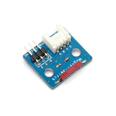
Electronic brick of magnetic switch can be connected to digital I/O port to obtain the current status of magnetic switch by reading the current digital signal. Generally speaking, output is high level; when the sensor encounters magnetic objects (such as magnet), output is low level.
Features
1. Plug and play, easy to use. Compatible with the mainstream 2.54 interfaces and 4-Pin Grove interfaces in the market.

2. With use of M4 standard fixed holes, compatible with M4-standard kits such as Lego and Makeblock.

3. Sensor is located on the edge of PCB to facilitate detection.

Specifications
| PCB size | 24.0mm X 21.0mm X 1.6mm |
| Working voltage | 3.3 or 5V DC |
| Operating voltage | 3.3 or 5V DC |
| Compatible interfaces | 2.54 3-pin interface and 4-pin Grove interface(1) |
Note 1: S for digital output port, V and G for voltage at the common collector and ground respectively.
Electrical Characteristics
| Parameter | Min. | Typical | Max. | Unit |
| Working voltage | 3 | 5 | 5.5 | VDC |
| Digital output voltage(VCC=5V) | 0 | - | 5 | V |
| Working current(VCC=5V) | - | 436 | - | uA |
Demo
Connect S port of electronic brick of magnetic switch to D2 port of Arduino board, and we will use the following program to read its digital value. If the digital value is high level, LED lamp will be ON; if the digital value is high level, LED lamp will be OFF.
 int magnet=2;       //connect tilt to D2
 int LED=13;
 void setup()
 {
 pinMode(LED, OUTPUT);
 pinMode(magnet, INPUT);
 }

 void loop()
 {
 if(digitalRead(magnet)==HIGH)   //when the digital output value of tilt is high, turn on the LED.
 {
   digitalWrite(LED, HIGH);
 }
 if(digitalRead(magnet)==LOW)    //when the digital output value of tilt is low, turn off the LED.
 {
   digitalWrite(LED, LOW);
 }
 }
 Notice