Difference between revisions of "Magnetic Sensor/Switch Brick"
(→Specifications) |
(→Electrical Characteristics) |
||
| Line 29: | Line 29: | ||
==Electrical Characteristics== | ==Electrical Characteristics== | ||
| + | {| class="wikitable" | ||
| + | |- | ||
| + | | align="center" style="background:#f0f0f0;"|'''Parameter''' | ||
| + | | align="center" style="background:#f0f0f0;"|'''Min.''' | ||
| + | | align="center" style="background:#f0f0f0;"|'''Typical''' | ||
| + | | align="center" style="background:#f0f0f0;"|'''Max.''' | ||
| + | | align="center" style="background:#f0f0f0;"|'''Unit''' | ||
| + | |- | ||
| + | | Working voltage||3||5||5.5||VDC | ||
| + | |- | ||
| + | | Digital output voltage(VCC=5V)||0||-||5||V | ||
| + | |- | ||
| + | | Working current(VCC=5V)||-||436||-||uA | ||
| + | |} | ||
==Demo== | ==Demo== | ||
Revision as of 03:25, 27 May 2014
Contents
Overview
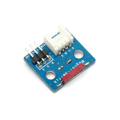
Electronic brick of magnetic switch can be connected to digital I/O port to obtain the current status of magnetic switch by reading the current digital signal. Generally speaking, output is high level; when the sensor encounters magnetic objects (such as magnet), output is low level.
Features
1. Plug and play, easy to use. Compatible with the mainstream 2.54 interfaces and 4-Pin Grove interfaces in the market.

2. With use of M4 standard fixed holes, compatible with M4-standard kits such as Lego and Makeblock.

3. Sensor is located on the edge of PCB to facilitate detection.

Specifications
| PCB size | 24.0mm X 21.0mm X 1.6mm |
| Working voltage | 3.3 or 5V DC |
| Operating voltage | 3.3 or 5V DC |
| Compatible interfaces | 2.54 3-pin interface and 4-pin Grove interface(1) |
Note 1: S for digital output port, V and G for voltage at the common collector and ground respectively.
Electrical Characteristics
| Parameter | Min. | Typical | Max. | Unit |
| Working voltage | 3 | 5 | 5.5 | VDC |
| Digital output voltage(VCC=5V) | 0 | - | 5 | V |
| Working current(VCC=5V) | - | 436 | - | uA |
 Notice