Difference between revisions of "ACS712 Current Sensor Brick"
(→Demo) |
(→Download) |
||
| Line 113: | Line 113: | ||
==Download== | ==Download== | ||
| + | [ftp://imall.iteadstudio.com/Electronic_Brick/IM120710011/DS_IM120710011.pdf Datasheet for ACS712 Current Sensor Brick] | ||
| + | |||
| + | [ftp://imall.iteadstudio.com/Electronic_Brick/IM120710011/SCH_IM120710011.pdf Schematic for ACS712 Current Sensor Brick] | ||
| + | |||
| + | [ftp://imall.iteadstudio.com/Electronic_Brick/IM120710011/DEMO_IM120710011.zip Demo code for ACS712 Current Sensor Brick] | ||
==Useful Links== | ==Useful Links== | ||
Revision as of 02:00, 27 May 2014
Contents
Overview
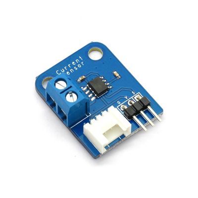
Electronic brick of current sensor is based on ACS712 sensor, which can accurately detect AC or DC signals. The maximum AC or DC that can be detected can reach 5A, and the present current signal can be read via analog I / O port.
Features
1. Plug and play, easy to use. Compatible with the mainstream 2.54 interfaces and 4-Pin Grove interfaces in the market.

2. With use of M4 standard fixed holes, compatible with M4-standard kits such as Lego and Makeblock.

3. Terminals with screws for easy wiring and removing.

Specifications
| PCB size | 30.0mm X 24.0mm X 1.6mm |
| Working voltage | 5V |
| Input current type | AC or DC |
| Compatible interfaces | 2.54 3-pin interface and 4-pin Grove interface(1) |
| Wiring interface | Power terminal(2) |
Note 1: S for analog output port, V and G for voltage at the common collector and ground respectively
Note 2: “+”for current inflow port“-”for current outflow port
Electrical Characteristics
| Parameter | Min. | Typical | Max. | Unit |
| Supply voltage | 4.5 | 5 | 5.5 | VDC |
| Working current(VCC=5V) | - | 10 | 13 | mA |
| Output impedance RLOAD(VIOUT to GND) | 4.7 | - | - | KΩ |
| Bandwidth(1) | - | 34 | - | Hz |
| Input current range | -5 | - | 5 | A |
| Sensitivity | 180 | 185 | 190 | mV/A |
Note 1: After removing C1, bandwidth can reach 80kHz

Relationship between output voltage and induced current
Demo
Connect S port of electronic brick of current sensor to A0 port of Arduino board, and we will use the following program to read the analog value and send it to the computer for display via serial port.
 #define CURRENT_SENSOR A0 // Analog input pin that sensor is attached to

 float amplitude_current;               //amplitude current
 float effective_value;       //effective current

 void setup()
 {
   Serial.begin(9600);
   pins_init();
 }
 void loop()
 {
   int sensor_max;
   sensor_max = getMaxValue();
   Serial.print("sensor_max = ");
   Serial.println(sensor_max);
   //the VCC on the Grove interface of the sensor is 5v
   amplitude_current=(float)(sensor_max-512)/1024*5/185*1000000;
   effective_value=amplitude_current/1.414;
   //minimum_current=1/1024*5/185*1000000/1.414=18.7(mA)
   //Only for sinusoidal alternating current
   Serial.println("The amplitude of the current is(in mA)");
   Serial.println(amplitude_current,1);//Only one number after the decimal point
   Serial.println("The effective value of the current is(in mA)");
   Serial.println(effective_value,1);
 }
 void pins_init()
 {
   pinMode(CURRENT_SENSOR, INPUT);
 }
 /*Function: Sample for 1000ms and get the maximum value from the S pin*/
 int getMaxValue()
 {
   int sensorValue;             //value read from the sensor
   int sensorMax = 0;
   uint32_t start_time = millis();
   while((millis()-start_time) < 1000)//sample for 1000ms
   {
       sensorValue = analogRead(CURRENT_SENSOR);
       if (sensorValue > sensorMax)
       {
           /*record the maximum sensor value*/
           sensorMax = sensorValue;
       }
   }
   return sensorMax;
 }
Download
Datasheet for ACS712 Current Sensor Brick
Schematic for ACS712 Current Sensor Brick
Demo code for ACS712 Current Sensor Brick
 Notice