Difference between revisions of "WIFI SHIELD REV2"
From ITEAD Wiki
(→Hardware) |
(→Pinmap) |
||
| Line 36: | Line 36: | ||
==Pinmap== | ==Pinmap== | ||
| + | |||
| + | ===Micro SD Socket=== | ||
| + | {| class="wikitable" | ||
| + | |- | ||
| + | | align="center" style="background:#f0f0f0;"|'''Index of Interface''' | ||
| + | | align="center" style="background:#f0f0f0;"|'''Name of Interface''' | ||
| + | | align="center" style="background:#f0f0f0;"|'''Index of Arduino''' | ||
| + | |- | ||
| + | | 1||SD_CS||D10 | ||
| + | |- | ||
| + | | 2||MOSI||D11 | ||
| + | |- | ||
| + | | 3||3V3 ||- | ||
| + | |- | ||
| + | | 4||SCK||D13 | ||
| + | |- | ||
| + | | 5||GND||- | ||
| + | |- | ||
| + | | 6||MISO||D12 | ||
| + | |} | ||
| + | |||
| + | ===WIFI module Interface=== | ||
| + | {| class="wikitable" | ||
| + | |- | ||
| + | | align="center" style="background:#f0f0f0;"|'''Index of Interface ''' | ||
| + | | align="center" style="background:#f0f0f0;"|'''Name of Interface''' | ||
| + | | align="center" style="background:#f0f0f0;"|'''Index of Arduino''' | ||
| + | |- | ||
| + | | 1||WIFI_RST||D9 | ||
| + | |- | ||
| + | | Index of Interface ||Name of Interface||Description | ||
| + | |- | ||
| + | | 1||D-RX ||Upgrade firmware, UART input | ||
| + | |- | ||
| + | | 2||D-TX ||Upgrade firmware, UART output | ||
| + | |- | ||
| + | | 3||ERROR||Severe error of module, high level is valid. | ||
| + | |- | ||
| + | | 4||WPS||WPS function input, descending portion is valid. If VDD/2 is input at the pin when starting, the module will enter WEB SERVER. | ||
| + | |- | ||
| + | | 5||BOOT||Used in boot program, high level is valid. | ||
| + | |- | ||
| + | | 6||RTS||UART requests sending | ||
| + | |- | ||
| + | | 7||CTS||UART clears sending | ||
| + | |} | ||
==UART Multiplexer== | ==UART Multiplexer== | ||
Revision as of 08:36, 26 May 2014
Contents
Overview
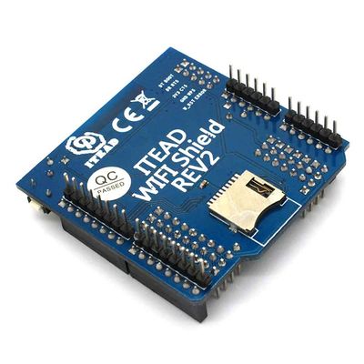
WIFI Shield REV2 supports IEEE 802.11b/g/n wireless protocol standard and serial output, which integrates TCP / IP protocol stack internally. It is specifically designed for Arduino boards including Arduino UNO, MEGA and Leonardo, and it supports 3.3V or 5V operation level so it can work with more Arduino-compatible boards.
Specifications
| PCB size | 58.0mm X 56mm X 1.6mm |
| Operation level | 3.3V or 5V |
| Indicator | PWR |
Electrical Characteristics
| Parameter | Min. | Typical | Max. | Unit |
| Power voltage | 3 | 3.3 | 3.6 | VDC |
| Working current (VCC=3.3V) | 0.5 | 15000 | 100000 | uA |
| Maximum radio frequency input (with reference to input of 50Ω) | - | 10 | - | dB |
| Static withstand voltage | - | - | 2000 | V |
Hardware

Pinmap
Micro SD Socket
| Index of Interface | Name of Interface | Index of Arduino |
| 1 | SD_CS | D10 |
| 2 | MOSI | D11 |
| 3 | 3V3 | - |
| 4 | SCK | D13 |
| 5 | GND | - |
| 6 | MISO | D12 |
WIFI module Interface
| Index of Interface | Name of Interface | Index of Arduino |
| 1 | WIFI_RST | D9 |
| Index of Interface | Name of Interface | Description |
| 1 | D-RX | Upgrade firmware, UART input |
| 2 | D-TX | Upgrade firmware, UART output |
| 3 | ERROR | Severe error of module, high level is valid. |
| 4 | WPS | WPS function input, descending portion is valid. If VDD/2 is input at the pin when starting, the module will enter WEB SERVER. |
| 5 | BOOT | Used in boot program, high level is valid. |
| 6 | RTS | UART requests sending |
| 7 | CTS | UART clears sending |
UART Multiplexer
Switch of operation level
Switch for transparent transmission
Indicator
- PWR, 3.3V supply indicator: when supply is normal, PWR indicator will keep ON.
Button
- WIFI_RST, WIFI resetting button: press the button to reset WIFI module.
Note
- There is no existing library to support the module at present.
 Notice