Difference between revisions of "ITEAD Arduino Sensor Shield"
(→pin Map) |
(→Installation) |
||
| Line 85: | Line 85: | ||
==Installation== | ==Installation== | ||
| + | ===Electronic brick interface=== | ||
| + | When connecting to 3-wire electronic brick with 2.54mm connection cable,please follow the way in the figures | ||
| + | below. The red frame indicates position for 3-pin connection cable, after connecting, electronic brick is linked to | ||
| + | D0 and A0 pin of the board. | ||
| + | |||
| + | [[File:Arduino sensor shield2.jpg]] | ||
| + | |||
| + | When connecting to 4-wire electronic brick with 2.54mm connection cable,please follow the way in the figures | ||
| + | below. The red frame indicates position for 4-pin connection cable, after connecting, electronic brick is linked to | ||
| + | D0 and D1, A0 and A1 pin of the board. | ||
| + | |||
| + | [[File:Arduino sensor shield3.jpg]] | ||
| + | |||
| + | ===Power switch=== | ||
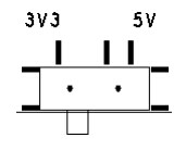
| + | It is used to switch the power supply VCC to the electronic brick. When switched to 3.3V, it indicates that VCC power | ||
| + | supply from the [[shield]] to the electronic brick is 3.3V; when switched to 5V, it indicates that VCC power supply from the | ||
| + | [[shield]] to the electronic brick is 5V. | ||
| + | |||
| + | [[File:Arduino sensor shield4.jpg]] | ||
| + | |||
| + | ===Reset button=== | ||
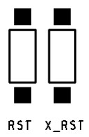
| + | Press RST button to reset Arduino board; press X_RST button to reset XB33 module. | ||
| + | |||
| + | [[File:Arduino sensor shield5.jpg]] | ||
==Download== | ==Download== | ||
==Useful Links== | ==Useful Links== | ||
Revision as of 07:51, 26 May 2014
Contents
Overview
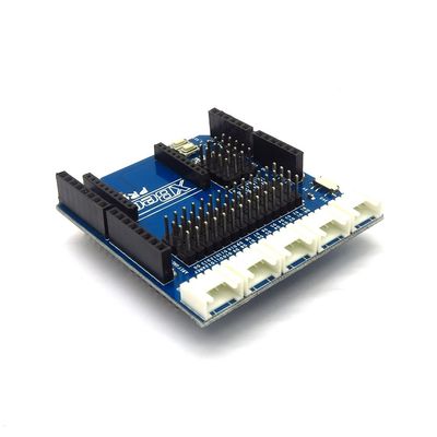
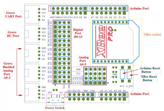
Arduino sensor shield is specifically designed for Arduino board to connect to various types of electronic brick modules. The latest version of shield can support electronic bricks with 3-wire and 4-wire communication, and it is compatible with the mainstream two interfaces of electronic bricks in the market: 2.0mm 4-pin grove interface and 2.54mm 3-pin interface. In addition, the shield is equipped with XBee interface for users to connect it with various external wireless modules which are compatible with XBee module interface. When working together with BTBee Pro, it can be used as a board.
Specifications
| PCB size | 61.0mm X 55.46mm X 1.6mm |
| Working voltage | 3.3/5V DC |
| Operating voltage | 3.3/5V DC |
| Compatible interfaces | 2.54 3/4-pin interface, Grove 4-pin interface(1) and XBee interface |
Note 1: V and G for voltage at the common collector and ground respectively
Hardware
pin Map
| Index of Interface | Name of Interface | Index of Arduino |
| 1 | D0 | D0 |
| 2 | D1 | D1 |
| 3 | D2 | D2 |
| 4 | D3 | D3 |
| 5 | D4 | D4 |
| 6 | D5 | D5 |
| 7 | D6 | D6 |
| 8 | D7 | D7 |
| 9 | D8 | D8 |
| 10 | D9 | D9 |
| 11 | D10 | D10 |
| 12 | D11 | D11 |
| 13 | D12 | D12 |
| 14 | D13 | D13 |
| 15 | AREF | AREF |
| 16 | A0 | A0 |
| 17 | A1 | A1 |
| 18 | A2 | A2 |
| 20 | A3 | A3 |
| 21 | A4 | A4 |
| 22 | A5 | A5 |
| 23 | TX | D1 |
| 24 | RX | D0 |
| 25 | SCL | A5 |
| 26 | SDA | A4 |
Installation
Electronic brick interface
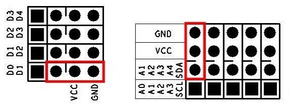
When connecting to 3-wire electronic brick with 2.54mm connection cable,please follow the way in the figures below. The red frame indicates position for 3-pin connection cable, after connecting, electronic brick is linked to D0 and A0 pin of the board.
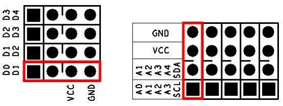
When connecting to 4-wire electronic brick with 2.54mm connection cable,please follow the way in the figures below. The red frame indicates position for 4-pin connection cable, after connecting, electronic brick is linked to D0 and D1, A0 and A1 pin of the board.
Power switch
It is used to switch the power supply VCC to the electronic brick. When switched to 3.3V, it indicates that VCC power supply from the shield to the electronic brick is 3.3V; when switched to 5V, it indicates that VCC power supply from the shield to the electronic brick is 5V.
Reset button
Press RST button to reset Arduino board; press X_RST button to reset XB33 module.
 Notice