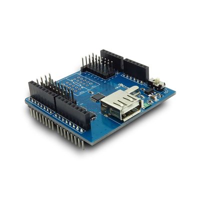
Difference between revisions of "Arduino USB Host Shield"
From ITEAD Wiki
(→Electrical Characteristics) |
(→Hardware) |
||
| Line 44: | Line 44: | ||
==Hardware== | ==Hardware== | ||
| + | http://imall.iteadstudio.com/media/wysiwyg/Products/IM120417019_Arduino_USB_Host_Shield/IM120417019_Arduino_USB_Host_Shield_1.jpg | ||
| + | |||
| + | Figure 1 Top Map | ||
| + | |||
| + | Arduino Socket defination: | ||
| + | {| class="wikitable" | ||
| + | |- | ||
| + | | align="center" style="background:#f0f0f0;"|'''Pin''' | ||
| + | | align="center" style="background:#f0f0f0;"|'''Description''' | ||
| + | |- | ||
| + | | D0||UART_Rx | ||
| + | |- | ||
| + | | D1||UART_Tx | ||
| + | |- | ||
| + | | D2||- | ||
| + | |- | ||
| + | | D3||- | ||
| + | |- | ||
| + | | D4||- | ||
| + | |- | ||
| + | | D5||- | ||
| + | |- | ||
| + | | D6||- | ||
| + | |- | ||
| + | | D7||- | ||
| + | |- | ||
| + | | D8||- | ||
| + | |- | ||
| + | | D9||- | ||
| + | |- | ||
| + | | D10||SPI-CSn | ||
| + | |- | ||
| + | | D11||SPI-MOSI | ||
| + | |- | ||
| + | | D12||SPI-MISO | ||
| + | |- | ||
| + | | D13||SPI-SCK | ||
| + | |- | ||
| + | | A0||AD0 | ||
| + | |- | ||
| + | | A1||AD1 | ||
| + | |- | ||
| + | | A2||AD2 | ||
| + | |- | ||
| + | | A3||AD3 | ||
| + | |- | ||
| + | | A4||IIC_SCL | ||
| + | |- | ||
| + | | A5||IIC_SDA | ||
| + | |} | ||
===GPIOx Break-out detail=== | ===GPIOx Break-out detail=== | ||
Revision as of 07:28, 23 May 2014
Contents
Overview
The USB Host Shield contains all of the digital logic and analog circuit necessary to implement a full-speed USB peripheral/host controller with Arduino. This shield adds USB Host capabilities to popular Arduino platform. C Software support for new devices is constantly added; at the moment, code for USB keyboard and PS3 controller are ready with Bluetooth and digital cameras in the works.
Features
- USB 2.0 Full Speed compatible
- 3.3/5V operation level compatible
- All GPIOx pins break-out
- USB Host 5V/500mA supply for USB protocol
Specifications
| PCB size | 56mm X 54mm X 1.6mm |
| Indicators | PWR |
| RoSH | Yes |
Electrical Characteristics
| Parameter | Min. | Typical | Max. | Unit |
| Power voltage (Vlogic) | 3 | 5.5 | VDC | |
| Input voltage VH | 0.7Vlogic | V | ||
| Input voltage VL | 0.3Vlogic | V | ||
| Current Consumption | 70 | mA |
Hardware

Figure 1 Top Map
Arduino Socket defination:
| Pin | Description |
| D0 | UART_Rx |
| D1 | UART_Tx |
| D2 | - |
| D3 | - |
| D4 | - |
| D5 | - |
| D6 | - |
| D7 | - |
| D8 | - |
| D9 | - |
| D10 | SPI-CSn |
| D11 | SPI-MOSI |
| D12 | SPI-MISO |
| D13 | SPI-SCK |
| A0 | AD0 |
| A1 | AD1 |
| A2 | AD2 |
| A3 | AD3 |
| A4 | IIC_SCL |
| A5 | IIC_SDA |
 Notice