Difference between revisions of "IE shield"
(→Electrical Characteristics) |
(→Hardware) |
||
| Line 55: | Line 55: | ||
==Hardware== | ==Hardware== | ||
| + | http://imall.iteadstudio.com/media/wysiwyg/Products/IM120417003_IEshield/IM120417003_IEshield.jpg | ||
| + | |||
| + | [[File:IEshield1.jpg]] | ||
| + | {| class="wikitable" | ||
| + | |- | ||
| + | | align="center" style="background:#f0f0f0;"|'''Interface''' | ||
| + | | align="center" style="background:#f0f0f0;"|'''Pin''' | ||
| + | | align="center" style="background:#f0f0f0;"|'''Description''' | ||
| + | |- | ||
| + | | UART||1||5V supply. | ||
| + | |- | ||
| + | | UART||2||Ground | ||
| + | |- | ||
| + | | UART||3||Tx | ||
| + | |- | ||
| + | | UART||4||Rx | ||
| + | |- | ||
| + | | GPI||1||5V supply. | ||
| + | |- | ||
| + | | GPI||2||Digital input pin | ||
| + | |- | ||
| + | | GPI||3||Ground | ||
| + | |- | ||
| + | | GPO||1||5V supply. | ||
| + | |- | ||
| + | | GPO||2||Digital output pin | ||
| + | |- | ||
| + | | GPO||3||Ground | ||
| + | |- | ||
| + | | DA||1||5V supply. | ||
| + | |- | ||
| + | | DA||2||Analog output pin | ||
| + | |- | ||
| + | | DA||3||Ground | ||
| + | |- | ||
| + | | PWM||1||5V supply. | ||
| + | |- | ||
| + | | PWM||2||PWM output pin | ||
| + | |- | ||
| + | | PWM||3||Ground | ||
| + | |- | ||
| + | | AD0/1/2||1||5V supply. | ||
| + | |- | ||
| + | | AD0/1/3||2||Analog input pin | ||
| + | |- | ||
| + | | AD0/1/4||3||Ground | ||
| + | |- | ||
| + | | IIC||1||5V supply. | ||
| + | |- | ||
| + | | IIC||2||Ground | ||
| + | |- | ||
| + | | IIC||3||Data wire of IIC | ||
| + | |- | ||
| + | | IIC||4||Clock wire of IIC | ||
| + | |- | ||
| + | | Ethernet module SPI||1||5V supply. | ||
| + | |- | ||
| + | | Ethernet module SPI||2||Ground | ||
| + | |- | ||
| + | | Ethernet module SPI||3||Chip select pin(Low active) | ||
| + | |- | ||
| + | | Ethernet module SPI||4||Chip reset pin(Low active) | ||
| + | |- | ||
| + | | Ethernet module SPI||5||Chip data input pin | ||
| + | |- | ||
| + | | Ethernet module SPI||6||Chip clock input pin | ||
| + | |- | ||
| + | | Ethernet module SPI||7||Weak on Line output pin(Low active) | ||
| + | |- | ||
| + | | Ethernet module SPI||8||Chip data output pin | ||
| + | |- | ||
| + | | Ethernet module SPI||9||Chip programmable clock output pin | ||
| + | |- | ||
| + | | Ethernet module SPI||10||Interrupt output pin(Low active) | ||
| + | |} | ||
==SPI_CSn Configuration== | ==SPI_CSn Configuration== | ||
==POE Configuration== | ==POE Configuration== | ||
Revision as of 02:23, 22 May 2014
Contents
Overview
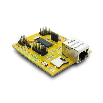
IE shield is an Ethernet Shield instantly enables internet connectivity for Arduino projects with ethernet controller ENC28J60. Just stack it onto an Arduino to create your own networked devices. Easily check connection status with on board indicator lights. Extend your design further with many Electronic / Sensor brick interface and an TF card socket.
This Ethernet shield support the POE function, you can use use the twisted-pair to power it and the Arduino board below, instead using the USB prower or external power jack supply. If your router or moden don't support POE, then you can use the injector cable to mix the signale and power for POE supply.
Features
- IEEE 802.3 compatible
- Supports POE*
- Integrated MAC and 10BASE-T PHY
- Receiver and collision squelch circuit
- Supports one 10BASE-T port with automatic polarity detection and correction
- Supports Full and Half-Duplex modes
- Programmable automatic retransmit on collision
- Programmable padding and CRC generation
- Programmable automatic rejection of erroneous packets
- Two programmable LED outputs for LINK, TX, RX, collision and full/half-duplex status
- Supports Micro-SD card with SPI operation
- Many analog and digital interfaces breakout include AD/DA/PWM/UART/IIC/GPIO
Specifications
| PCB size | 55.8mm X 68.8mm X 1.6mm |
| Indicators | PWR State |
| Power supply | 5V DC, POE 12V |
| Communication Protocol | Ethernet, UART, IIC, SPI |
| RoSH | Yes |
Electrical Characteristics
| Specification | Min | Type | Max | Unit |
| Power Voltage(VCC) | 4.5 | 5 | 5.5 | VDC |
| Power Voltage(POE) | 7 | - | 20 | VDC |
| Input Voltage VH: | 4.5 | 5 | 5.5 | V |
| Input Voltage VL: | -0.3 | 0 | 0.5 | V |
| Current Consumption | - | 100 | 200 | mA |
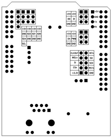
Hardware

| Interface | Pin | Description |
| UART | 1 | 5V supply. |
| UART | 2 | Ground |
| UART | 3 | Tx |
| UART | 4 | Rx |
| GPI | 1 | 5V supply. |
| GPI | 2 | Digital input pin |
| GPI | 3 | Ground |
| GPO | 1 | 5V supply. |
| GPO | 2 | Digital output pin |
| GPO | 3 | Ground |
| DA | 1 | 5V supply. |
| DA | 2 | Analog output pin |
| DA | 3 | Ground |
| PWM | 1 | 5V supply. |
| PWM | 2 | PWM output pin |
| PWM | 3 | Ground |
| AD0/1/2 | 1 | 5V supply. |
| AD0/1/3 | 2 | Analog input pin |
| AD0/1/4 | 3 | Ground |
| IIC | 1 | 5V supply. |
| IIC | 2 | Ground |
| IIC | 3 | Data wire of IIC |
| IIC | 4 | Clock wire of IIC |
| Ethernet module SPI | 1 | 5V supply. |
| Ethernet module SPI | 2 | Ground |
| Ethernet module SPI | 3 | Chip select pin(Low active) |
| Ethernet module SPI | 4 | Chip reset pin(Low active) |
| Ethernet module SPI | 5 | Chip data input pin |
| Ethernet module SPI | 6 | Chip clock input pin |
| Ethernet module SPI | 7 | Weak on Line output pin(Low active) |
| Ethernet module SPI | 8 | Chip data output pin |
| Ethernet module SPI | 9 | Chip programmable clock output pin |
| Ethernet module SPI | 10 | Interrupt output pin(Low active) |
 Notice
