Difference between revisions of "ITDB02-2.4E V2"
m (→Overview) |
m (→Overview) |
||
| Line 6: | Line 6: | ||
'''NOTE:''' this screen adopts new driver IC, thus the old library is not applicable. Please use the [https://github.com/itead/ITEADLIB_Arduino_UTFT_Pro New UTFT Library]. | '''NOTE:''' this screen adopts new driver IC, thus the old library is not applicable. Please use the [https://github.com/itead/ITEADLIB_Arduino_UTFT_Pro New UTFT Library]. | ||
| − | Go shopping [https://www.itead.cc/itdb02-2-4e-v2.html ITDB02-2.4E | + | Go shopping [https://www.itead.cc/itdb02-2-4e-v2.html ITDB02-2.4E V2(IM160418002)] |
==Features== | ==Features== | ||
Revision as of 10:54, 29 June 2016
Overview
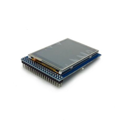
ITDB02-2.4E V2 module is 2.4" TFT LCD with 65K color 320 x 240 resolutions. The controller of this LCD module is ILI9341, it supports 8bit / 16bit data interface with 4 wires control interface. Moreover, this module includes the touch screen and SD card socket.
NOTE: this screen adopts new driver IC, thus the old library is not applicable. Please use the New UTFT Library.
Go shopping ITDB02-2.4E V2(IM160418002)
Features
- 8bits/16bits operation compatible
- Compatible with new UTFT library
- With SD Card Socket
Specifications
| Driver IC | ILI9341 |
| Backlight | 4LEDs |
| Power supply | 3V3 |
| Touch Panel | Y |
| Touch IC | XPT2046 |
| Resolution | 240*320 |
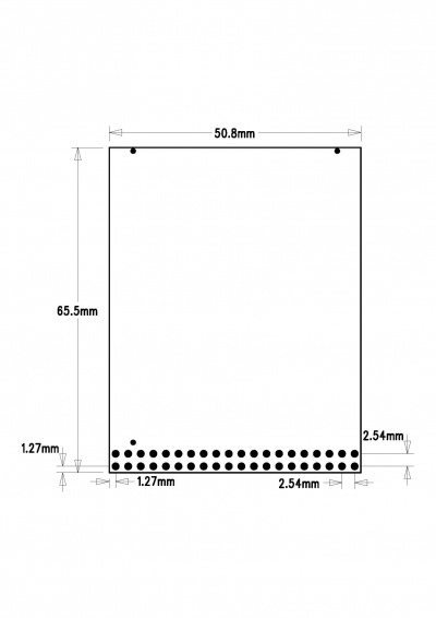
| Size | 50mm*65mm |
Hardware
Pin Map list
| Pin | Type* | Description |
| GND | G | Ground |
| VCC | P | 5V Power Supply pin |
| NC | - | No connection |
| RS | I | Data/Command selection |
| WR | I | Write signal enable, low active |
| RD | I | Read signal enable, low active |
| DB8 | I | Data Bus |
| DB9 | I | Data Bus |
| DB10 | I | Data Bus |
| DB11 | I | Data Bus |
| DB12 | I | Data Bus |
| DB13 | I | Data Bus |
| DB14 | I | Data Bus |
| DB15 | I | Data Bus |
| CS | I | Chip Selection,Low level active |
| NC | - | No connection |
| LED | P | Backlight |
| NC | - | No connection |
| DB0 | - | No connection(8bit mode) |
| DB0 | I | Data Bus(16bit mode) |
| DB1 | - | No connection(8bit mode) |
| DB1 | I | Data Bus(16bit mode) |
| DB2 | - | No connection(8bit mode) |
| DB2 | I | Data Bus(16bit mode) |
| DB3 | - | No connection(8bit mode) |
| DB3 | I | Data Bus(16bit mode) |
| DB4 | - | No connection(8bit mode) |
| DB4 | I | Data Bus(16bit mode) |
| DB5 | - | No connection(8bit mode) |
| DB5 | I | Data Bus(16bit mode) |
| DB6 | - | No connection(8bit mode) |
| DB6 | I | Data Bus(16bit mode) |
| DB7 | - | No connection(8bit mode) |
| DB7 | I | Data Bus(16bit mode) |
| T_CLK | I | Touch clock |
| T_CS | I | Touch chip selection |
| T_DIN | I | Touch data input |
| T_BUSY | O | Touch status |
| T_DOUT | O | Touch data output |
| T_IRQ | O | Touch interrupt |
| SD_SO | O | SD MISO |
| SD_SCK | I | SD SCK |
| SD_SI | I | SD MOSI |
| SD_NSS | I | SD NSS |
| NC | - | No connection |
| NC | - | No connection |
Type *:P: Power supply; G:Ground; I:Input; O:Output;
The ITDB02_2.4E uses the ILI9341 controller, it support 8/16bit data interface. The touch IC is TSC2046.
Installation
When operate in 8 bits mode, the mode switch need to set in 8bits side.
When operate in 16 bits mode, the mode switch need to set in 16bits side.
 Notice

