Difference between revisions of "ITDB02-2.4S"
m |
(Marked this version for translation) |
||
| Line 1: | Line 1: | ||
<translate> | <translate> | ||
| − | ==Overview== | + | ==Overview== <!--T:1--> |
[[File:IM140714002_5.jpg|thumb|400px|right]] | [[File:IM140714002_5.jpg|thumb|400px|right]] | ||
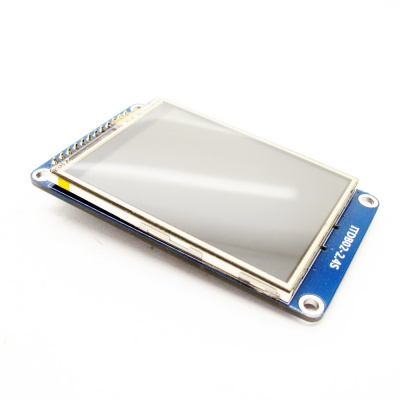
ITDB02-2.4S module is 2.4" SPI TFT LCD with 262K color 320 x 240 resolutions. The controller chip of this LCD module is ILI9341V. Since its interface is SPI, you need 6 Dupont lines (SCK,MISO,MOSI,CS,D/C,RST) to control the LCD module. Moreover, there is an on-board micro SD card slot for multimedia storage and data logging purposes. This 2.4" LCD is a resistive touchscreen as well, so you can detect finger presses anywhere on the screen. | ITDB02-2.4S module is 2.4" SPI TFT LCD with 262K color 320 x 240 resolutions. The controller chip of this LCD module is ILI9341V. Since its interface is SPI, you need 6 Dupont lines (SCK,MISO,MOSI,CS,D/C,RST) to control the LCD module. Moreover, there is an on-board micro SD card slot for multimedia storage and data logging purposes. This 2.4" LCD is a resistive touchscreen as well, so you can detect finger presses anywhere on the screen. | ||
| + | <!--T:2--> | ||
Go shopping [http://imall.iteadstudio.com/itdb02-2-4s.html ITDB02-2.4S (SKU:IM140714002)] | Go shopping [http://imall.iteadstudio.com/itdb02-2-4s.html ITDB02-2.4S (SKU:IM140714002)] | ||
| − | ==Features== | + | ==Features== <!--T:3--> |
*Compatible for 3.3/5V operating level | *Compatible for 3.3/5V operating level | ||
*Integrated with an micro SD card slot | *Integrated with an micro SD card slot | ||
| Line 12: | Line 13: | ||
*Resistive touchscreen | *Resistive touchscreen | ||
| − | ==Specification== | + | ==Specification== <!--T:4--> |
{| border="1" | {| border="1" | ||
| PCB size||44mm X 74mm X 1.6mm | | PCB size||44mm X 74mm X 1.6mm | ||
| Line 24: | Line 25: | ||
|} | |} | ||
| − | ==Electronic Characteristics== | + | ==Electronic Characteristics== <!--T:5--> |
{| class="wikitable" | {| class="wikitable" | ||
|- | |- | ||
| Line 44: | Line 45: | ||
|} | |} | ||
| − | ==Hardware== | + | ==Hardware== <!--T:6--> |
[[File:IM140714002pic1.jpg|500px]] | [[File:IM140714002pic1.jpg|500px]] | ||
[[File:IM140714002pic2.jpg|500px]] | [[File:IM140714002pic2.jpg|500px]] | ||
[[File:IM140714002pic3.jpg|500px]] | [[File:IM140714002pic3.jpg|500px]] | ||
| − | ==Pin Map== | + | ==Pin Map== <!--T:7--> |
{| class="wikitable" | {| class="wikitable" | ||
|- | |- | ||
| Line 84: | Line 85: | ||
*LEDA: When LEDA is set as high electronic level, the backlight turns on. When it's set as low electronic level, the backlight turns off. | *LEDA: When LEDA is set as high electronic level, the backlight turns on. When it's set as low electronic level, the backlight turns off. | ||
| − | ==Instruction== | + | ==Instruction== <!--T:8--> |
| + | <!--T:9--> | ||
<big>'''1.Touch Function'''</big> | <big>'''1.Touch Function'''</big> | ||
*Upload '''2_4_spi_touch.ino''' into UNO main board | *Upload '''2_4_spi_touch.ino''' into UNO main board | ||
| Line 123: | Line 125: | ||
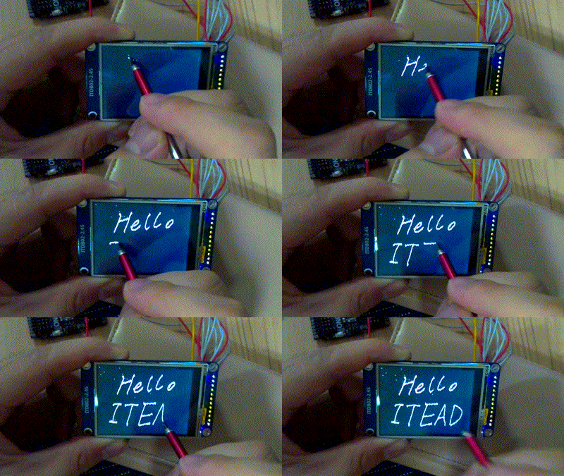
[[File:IM140714002in2.gif|400px]] | [[File:IM140714002in2.gif|400px]] | ||
| + | <!--T:10--> | ||
<big>'''2.Display the image from micro SD card'''</big> | <big>'''2.Display the image from micro SD card'''</big> | ||
*[[Download]] the library from this link: https://github.com/adafruit/Adafruit_ILI9340 , then extract it into the directory '''\arduino\libraries''' | *[[Download]] the library from this link: https://github.com/adafruit/Adafruit_ILI9340 , then extract it into the directory '''\arduino\libraries''' | ||
| − | *Copy the image '''woof.bmp''' from the directory '''Adafruit_ILI9340\examples\spitftbitmap''' to your SD card, then plug the card into the SD card slot on ITDB02-2.2S LCD module | + | *Copy the image '''woof.bmp''' from the directory '''Adafruit_ILI9340\examples\spitftbitmap''' to your SD card, then plug the card into the SD card slot on [[ITDB02-2.2S]] LCD module |
*Use arduino IDE to open '''spitftbitmap.ino''' in the directory '''Adafruit_ILI9340\examples\spitftbitmap''' then upload it to UNO main board. | *Use arduino IDE to open '''spitftbitmap.ino''' in the directory '''Adafruit_ILI9340\examples\spitftbitmap''' then upload it to UNO main board. | ||
*Select 5V electronic level in the 2.2S LCD module, then use dupont lines to connect UNO and LCD module according to the table as below: | *Select 5V electronic level in the 2.2S LCD module, then use dupont lines to connect UNO and LCD module according to the table as below: | ||
| Line 156: | Line 159: | ||
*Power UNO main board, a picture of dog showed on the display. | *Power UNO main board, a picture of dog showed on the display. | ||
| − | ==Download== | + | ==Download== <!--T:11--> |
Specification for TFT LCD module--[[:File:H24TM84A-spec.pdf]] | Specification for TFT LCD module--[[:File:H24TM84A-spec.pdf]] | ||
| + | <!--T:12--> | ||
Schematic--[[:File:IM140714002-ITDB02-2.4S-schematic.pdf]] | Schematic--[[:File:IM140714002-ITDB02-2.4S-schematic.pdf]] | ||
| − | ==Useful Link== | + | ==Useful Link== <!--T:13--> |
https://github.com/adafruit/Adafruit_ILI9340 | https://github.com/adafruit/Adafruit_ILI9340 | ||
</translate> | </translate> | ||
Revision as of 01:38, 9 August 2014
Contents
Overview
ITDB02-2.4S module is 2.4" SPI TFT LCD with 262K color 320 x 240 resolutions. The controller chip of this LCD module is ILI9341V. Since its interface is SPI, you need 6 Dupont lines (SCK,MISO,MOSI,CS,D/C,RST) to control the LCD module. Moreover, there is an on-board micro SD card slot for multimedia storage and data logging purposes. This 2.4" LCD is a resistive touchscreen as well, so you can detect finger presses anywhere on the screen.
Go shopping ITDB02-2.4S (SKU:IM140714002)
Features
- Compatible for 3.3/5V operating level
- Integrated with an micro SD card slot
- Support IO/PMW to control the backlight
- Resistive touchscreen
Specification
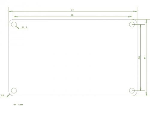
| PCB size | 44mm X 74mm X 1.6mm |
| Power supply | 5V DC |
| Driver IC | ILI9341V |
| Resolution | 320*240 |
Electronic Characteristics
| Parameter | Min. | Typical | Max. | Unit |
| Power supply | 4.5 | 5 | 5.5 | VDC |
| Input voltage VinH (Target Voltage = 3.3V) | 3 | 3.3 | 3.6 | V |
| Input voltage VinH (Target Voltage = 5V) | 4.5 | 5 | 5.5 | V |
| Input voltage VinL | -0.3 | 0 | 0.5 | V |
| Current Consumption | - | 40 | 80 | mA |
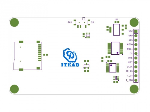
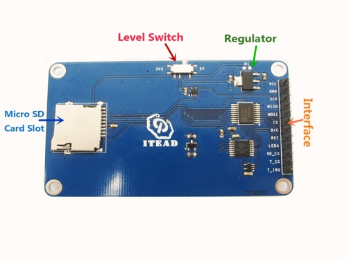
Hardware
Pin Map
| Pin | Type* | Description |
| VCC | P | 5V Power supply pin |
| GND | G | Ground |
| SCK | I | SPI SCK |
| MISO | O | SPI MISO |
| MOSI | I | SPI MOSI |
| CS | I | Chip Select for TFT |
| D/C | I | Command or parameter select |
| RST | I | RESET signal for TFT |
| LEDA* | I | Backlight control pin |
| SD_CS | I | Chip Select for SD |
| T_CS | I | Chip Select for touch function |
| T_IRQ | O | Interrupt output for touch |
- Type: P--Power supply; G--Ground; I--Input; O--Output.
- LEDA: When LEDA is set as high electronic level, the backlight turns on. When it's set as low electronic level, the backlight turns off.
Instruction
1.Touch Function
- Upload 2_4_spi_touch.ino into UNO main board
- Connect ITDB02-2.4S module to UNO according to the table as below:
| 2.4S pins | UNO pins |
| VCC | 5V |
| GND | GND |
| SCK | D13 |
| MISO | D12 |
| MOSI | D11 |
| CS | D10 |
| D/C | D9 |
| RST | D8 |
| LEDA | 5V/3V3 |
| SD_CS | D4 |
| T_CS | D2 |
| T_IRQ | D3 |
- Power UNO mainboard, you can start to draw any line or pattern on the screen.
2.Display the image from micro SD card
- Download the library from this link: https://github.com/adafruit/Adafruit_ILI9340 , then extract it into the directory \arduino\libraries
- Copy the image woof.bmp from the directory Adafruit_ILI9340\examples\spitftbitmap to your SD card, then plug the card into the SD card slot on ITDB02-2.2S LCD module
- Use arduino IDE to open spitftbitmap.ino in the directory Adafruit_ILI9340\examples\spitftbitmap then upload it to UNO main board.
- Select 5V electronic level in the 2.2S LCD module, then use dupont lines to connect UNO and LCD module according to the table as below:
| 2.4S pins | UNO pins |
| VCC | 5V |
| GND | GND |
| SCK | D13 |
| MISO | D12 |
| MOSI | D11 |
| CS | D10 |
| D/C | D9 |
| RST | D8 |
| LEDA | 5V/3V3 |
| SD_CS | D4 |
- Power UNO main board, a picture of dog showed on the display.
Download
Specification for TFT LCD module--File:H24TM84A-spec.pdf
Schematic--File:IM140714002-ITDB02-2.4S-schematic.pdf
 Notice