Difference between revisions of "128 X 64 OLED MODULE"
m (→Overview) |
m (→Hardware) |
||
| Line 37: | Line 37: | ||
==Hardware== | ==Hardware== | ||
| + | |||
| + | [[File:IM130625003pic1.png|500px]] | ||
| + | |||
http://imall.iteadstudio.com/media/wysiwyg/Products/Graphic_Display/IM130625003_1.jpg | http://imall.iteadstudio.com/media/wysiwyg/Products/Graphic_Display/IM130625003_1.jpg | ||
Revision as of 02:23, 18 May 2015
Contents
Overview
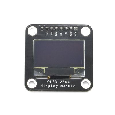
OLED 2864 display module can work without backlight. In a dark environment, contrast of OLED display is higher compared to that of LCD display, and OLED is thinner and lighter. OLED 2864 is a monochrome graphic display module with built-in 0.96 inch, 128X64 high-resolution display. Driver chip of OLED module is SSD1306, which is compatible with IIC or SPI communication interface greatly reducing the IO port occupation. OLED module can be used in various commercial applications, such as display of mobile phones, portable digital media players, radio and digital cameras, and so.
Attention: This module can't be driven by 5V level mainboard in case it burns out.
Go shopping 128 X 64 OLED MODULE (IM130625003)
Specifications
| PCB size | 35.5mm X 35.5mm X 1.6mm |
| Working voltage | 3.3V |
| Compatible interfaces | IIC (default ) or SPI |
| IIC address | 0x3C: D/C pin grounded; 0x3D: D/C pin connected to 3.3V |
Electrical Characteristics
| Specification | Min | Type | Max | Unit |
| Power Voltage | 1.65 | 3.3 | 3.3 | VDC |
| Working voltage (VCC=3.3V) | 20 | mA | ||
| Logic input voltage | Vss-0.3 | Vss+0.3 | dB |
Hardware

Pin map
| Pin | Pin name | Communication | Description |
| 1 | VCC | - | Voltage at the common collector |
| 2 | GND | - | Ground |
| 3 | CS | - | Chip selection pin |
| 4 | RES | - | Reset pin |
| 5 | D/C | - | Data/command selection pin |
| 6 | SDA | IIC | Data input pin |
| 6 | SDIN | SPI | Data input pin |
| 7 | SCL | IIC | Data clock pin |
| 7 | SCLK | SPI | Data clock pin |
| 8 | NC | - | Not connected pin |
Communication Interface Settings
OLED display module supports IIC or SPI communication with default as IIC. If you want to use SPI communication, following settings will be needed:
Remove resistors on R3, R4, R5, and R7, and weld a 0R resistor on R8.
Download
Datasheet for 128 X 64 OLED MODULE
 Notice
