Difference between revisions of "IBridge"
From ITEAD Wiki
(→Specifications) |
(→Overview) |
||
| (9 intermediate revisions by the same user not shown) | |||
| Line 3: | Line 3: | ||
[[File:Ibridge.jpg|thumb|400px|right]] | [[File:Ibridge.jpg|thumb|400px|right]] | ||
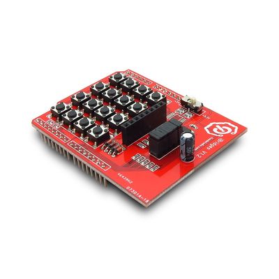
IBridge is a 4X4 key-pad [[shield]] with a 5110 Graphic LCD interface.You can plug it on Arduino boards directly, and you can get the small development platform with keypad input and Graphic LCD display. | IBridge is a 4X4 key-pad [[shield]] with a 5110 Graphic LCD interface.You can plug it on Arduino boards directly, and you can get the small development platform with keypad input and Graphic LCD display. | ||
| + | |||
| + | Go shopping [http://imall.iteadstudio.com/im120417001.html IBridge (IM120417001)] | ||
==Specifications== | ==Specifications== | ||
| Line 15: | Line 17: | ||
==Electrical Characteristics== | ==Electrical Characteristics== | ||
| + | {| class="wikitable" | ||
| + | |- | ||
| + | | align="center" style="background:#f0f0f0;"|'''Specification''' | ||
| + | | align="center" style="background:#f0f0f0;"|'''Min''' | ||
| + | | align="center" style="background:#f0f0f0;"|'''Type''' | ||
| + | | align="center" style="background:#f0f0f0;"|'''Max''' | ||
| + | | align="center" style="background:#f0f0f0;"|'''Unit''' | ||
| + | |- | ||
| + | | Power Voltage||4.5||5||5.5||VDC | ||
| + | |- | ||
| + | | Input Voltage VH (Target Voltage = 3.3V)||3||3.3||3.6||V | ||
| + | |- | ||
| + | | Input Voltage VH (Target Voltage = 5V)||4.5||5||5.5|| | ||
| + | |- | ||
| + | | Input Voltage VL: ||-0.3||0||0.5||V | ||
| + | |- | ||
| + | | Current Consumption(Except Motor Drive Current)||-||20||40||mA | ||
| + | |} | ||
==Hardware== | ==Hardware== | ||
| + | http://imall.iteadstudio.com/media/wysiwyg/Products/IM120417001_IBridge/IM120417001_Ibridge_pin.jpg | ||
| + | |||
| + | {| class="wikitable" | ||
| + | |- | ||
| + | | align="center" style="background:#f0f0f0;"|'''Zone''' | ||
| + | | align="center" style="background:#f0f0f0;"|'''Name''' | ||
| + | | align="center" style="background:#f0f0f0;"|'''Description''' | ||
| + | |- | ||
| + | | 1||Switch||Set the keypad input level | ||
| + | |- | ||
| + | | 2||Jumper||Fix the voltage level that LCD work with | ||
| + | |- | ||
| + | | 3||LCD5110 socket ||Interface for LCD5110 | ||
| + | |- | ||
| + | | 4||Keyboard Zone||16 buttons in scan keyboard | ||
| + | |} | ||
==Pins description== | ==Pins description== | ||
| + | {| class="wikitable" | ||
| + | |- | ||
| + | | align="center" style="background:#f0f0f0;"|'''Pin''' | ||
| + | | align="center" style="background:#f0f0f0;"|'''Pad Name''' | ||
| + | | align="center" style="background:#f0f0f0;"|'''Type''' | ||
| + | | align="center" style="background:#f0f0f0;"|'''Description''' | ||
| + | |- | ||
| + | | P3||Row2||I||Scan key-board row line 2 | ||
| + | |- | ||
| + | | P4||Row3||I||Scan key-board row line 3 | ||
| + | |- | ||
| + | | P5||Column0||O||Scan key-board column line 0 | ||
| + | |- | ||
| + | | P6||Column1||O||Scan key-board column line 1 | ||
| + | |- | ||
| + | | P7||Column2||O||Scan key-board column line 2 | ||
| + | |- | ||
| + | | P8||Column3||O||Scan key-board column line 3 | ||
| + | |- | ||
| + | | P9||SCK||O||LCD5110 clock | ||
| + | |- | ||
| + | | P10||MO||O||LCD5110 data | ||
| + | |- | ||
| + | | P11||D/Cn||O||LCD5110 data/command select | ||
| + | |- | ||
| + | | P12||RSTn||O||LCD5110 reset | ||
| + | |- | ||
| + | | P13||CSn||O||LCD5110 chip select | ||
| + | |- | ||
| + | | P17||Row0||I||Scan key-board row line 0 | ||
| + | |- | ||
| + | | P18||Row1||I||Scan key-board row line 1 | ||
| + | |- | ||
| + | | P24||GND||G|| | ||
| + | |- | ||
| + | | P25||GND||G|| | ||
| + | |- | ||
| + | | P26||VCC||P|| | ||
| + | |} | ||
===Switch description=== | ===Switch description=== | ||
| + | {| class="wikitable" | ||
| + | |- | ||
| + | | align="center" style="background:#f0f0f0;"|'''Switch''' | ||
| + | | align="center" style="background:#f0f0f0;"|'''Description''' | ||
| + | |- | ||
| + | | 3.3V||Work with 3.3V system, like IFLAT32 | ||
| + | |- | ||
| + | | 5V||Work with 5V system, like Arduino , Iteaduino | ||
| + | |} | ||
| + | |||
===Jumper description=== | ===Jumper description=== | ||
| + | {| class="wikitable" | ||
| + | |- | ||
| + | | align="center" style="background:#f0f0f0;"|'''Jumper''' | ||
| + | | align="center" style="background:#f0f0f0;"|'''Description''' | ||
| + | |- | ||
| + | | All||Work with 3.3V system, like IFLAT32 | ||
| + | |- | ||
| + | | None||Work with 5V system, like Arduino , Iteaduino | ||
| + | |} | ||
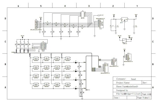
==Schematic== | ==Schematic== | ||
| + | [[File:Ibridge1.jpg]] | ||
| + | |||
| + | ==Download== | ||
| + | [ftp://imall.iteadstudio.com/IM120417001_IBridge/DS_IM120417001_IBridge.pdf Datasheet for IBridge] | ||
| + | |||
| + | [ftp://imall.iteadstudio.com/IM120417001_IBridge/SCH_IM120417001_IBridge.pdf Schematic for IBridge] | ||
| + | |||
| + | [ftp://imall.iteadstudio.com/IM120417001_IBridge/DC_IM120417001_IBridge.zip Demo Code for IBridge] | ||
| + | |||
| + | ==Useful Links== | ||
| + | [http://www.elektor-projects.com/project/poor-man-s-multichannel-data-logger.12553.html by JvK <Poor man 's multichannel data logger>] | ||
Latest revision as of 06:00, 11 June 2014
Contents
Overview
IBridge is a 4X4 key-pad shield with a 5110 Graphic LCD interface.You can plug it on Arduino boards directly, and you can get the small development platform with keypad input and Graphic LCD display.
Go shopping IBridge (IM120417001)
Specifications
| PCB size | 53.3mm X 68.6mm X 1.6mm |
| Power supply | 5V DC |
| RoSH | Yes |
Electrical Characteristics
| Specification | Min | Type | Max | Unit |
| Power Voltage | 4.5 | 5 | 5.5 | VDC |
| Input Voltage VH (Target Voltage = 3.3V) | 3 | 3.3 | 3.6 | V |
| Input Voltage VH (Target Voltage = 5V) | 4.5 | 5 | 5.5 | |
| Input Voltage VL: | -0.3 | 0 | 0.5 | V |
| Current Consumption(Except Motor Drive Current) | - | 20 | 40 | mA |
Hardware

| Zone | Name | Description |
| 1 | Switch | Set the keypad input level |
| 2 | Jumper | Fix the voltage level that LCD work with |
| 3 | LCD5110 socket | Interface for LCD5110 |
| 4 | Keyboard Zone | 16 buttons in scan keyboard |
Pins description
| Pin | Pad Name | Type | Description |
| P3 | Row2 | I | Scan key-board row line 2 |
| P4 | Row3 | I | Scan key-board row line 3 |
| P5 | Column0 | O | Scan key-board column line 0 |
| P6 | Column1 | O | Scan key-board column line 1 |
| P7 | Column2 | O | Scan key-board column line 2 |
| P8 | Column3 | O | Scan key-board column line 3 |
| P9 | SCK | O | LCD5110 clock |
| P10 | MO | O | LCD5110 data |
| P11 | D/Cn | O | LCD5110 data/command select |
| P12 | RSTn | O | LCD5110 reset |
| P13 | CSn | O | LCD5110 chip select |
| P17 | Row0 | I | Scan key-board row line 0 |
| P18 | Row1 | I | Scan key-board row line 1 |
| P24 | GND | G | |
| P25 | GND | G | |
| P26 | VCC | P |
Switch description
| Switch | Description |
| 3.3V | Work with 3.3V system, like IFLAT32 |
| 5V | Work with 5V system, like Arduino , Iteaduino |
Jumper description
| Jumper | Description |
| All | Work with 3.3V system, like IFLAT32 |
| None | Work with 5V system, like Arduino , Iteaduino |
 Notice
