Difference between revisions of "PSH-C32"
m |
m |
||
| (11 intermediate revisions by the same user not shown) | |||
| Line 4: | Line 4: | ||
Go shopping [http://itead.cc/psh-c32.html PSH-C32 WiFi Wireless Module(SKU: IM160913001)] | Go shopping [http://itead.cc/psh-c32.html PSH-C32 WiFi Wireless Module(SKU: IM160913001)] | ||
| + | |||
| + | ==Features== | ||
| + | *Support wireless 802.11 b/g/n/e/i | ||
| + | *IEEE 802.11 standard security features all supported,including WFA/WPA/WPA2/WAPI | ||
| + | *Support WPA/WPA2 /WP2-Enterprise /WPS encryption | ||
| + | *Built-in TCP/IP protocol stack, support multi-way TCP Client connection | ||
| + | *Support Wi-Fi Direct (P2P),P2P discovery,P2P GO mode and P2P power management | ||
| + | *Bluetooth v4.2 complete standard, including BR/EDR and BLE | ||
| + | *Support standard Class-1, Class-2, Class-3 without need for external power amplifier | ||
| + | *Support rich Socket AT command | ||
| + | *Support SDK fast programming | ||
| + | *Support UART/GPIO data communication interface | ||
| + | *Built-in 32-bit MCU, can also serve as the application processor | ||
| + | *Supply voltage: 2.2V~3.6V, default single 3.3V power supply | ||
==Electrical Characteristics== | ==Electrical Characteristics== | ||
| Line 19: | Line 33: | ||
| I/O Imax || || || 12 || mA | | I/O Imax || || || 12 || mA | ||
|} | |} | ||
| − | == | + | ==Hardware== |
| + | [[File:PSH-C32-dimension.docx.jpg|500px]] | ||
| + | ==PIN== | ||
===PIN MAP=== | ===PIN MAP=== | ||
| + | [[File:ESP32.jpg|300px]] | ||
| + | |||
| + | {| class="wikitable" | ||
| + | ! scope="col" | PIN || scope="col" | Name | ||
| + | |- | ||
| + | | style="text-align:right" | 1 || CHIP_PU | ||
| + | |- | ||
| + | | style="text-align:right" | 2 || SENSOR_VP | ||
| + | |- | ||
| + | | style="text-align:right" | 3 || SENSOR_CAPP | ||
| + | |- | ||
| + | | style="text-align:right" | 4 || SENSOR_CAPN | ||
| + | |- | ||
| + | | style="text-align:right" | 5 || SENSOR_VN | ||
| + | |- | ||
| + | | style="text-align:right" | 6 || VDET_1 | ||
| + | |- | ||
| + | | style="text-align:right" | 7 || VDET_2 | ||
| + | |- | ||
| + | | style="text-align:right" | 8 || 32K_XP | ||
| + | |- | ||
| + | | style="text-align:right" | 9 || 32K_XN | ||
| + | |- | ||
| + | | style="text-align:right" | 10 || GPIO25 | ||
| + | |- | ||
| + | | style="text-align:right" | 11 || GPIO26 | ||
| + | |- | ||
| + | | style="text-align:right" | 12 || GPIO27 | ||
| + | |- | ||
| + | | style="text-align:right" | 13 || GND | ||
| + | |- | ||
| + | | style="text-align:right" | 14 || GND | ||
| + | |- | ||
| + | | style="text-align:right" | 15 || MTMS | ||
| + | |- | ||
| + | | style="text-align:right" | 16 || MTDI | ||
| + | |- | ||
| + | | style="text-align:right" | 17 || MTCK | ||
| + | |- | ||
| + | | style="text-align:right" | 18 || MTDO | ||
| + | |- | ||
| + | | style="text-align:right" | 19 || GPIO2 | ||
| + | |- | ||
| + | | style="text-align:right" | 20 || GPIO0 | ||
| + | |- | ||
| + | | style="text-align:right" | 21 || GPIO4 | ||
| + | |- | ||
| + | | style="text-align:right" | 22 || GPIO16 | ||
| + | |- | ||
| + | | style="text-align:right" | 23 || GPIO17 | ||
| + | |- | ||
| + | | style="text-align:right" | 24 || NC | ||
| + | |- | ||
| + | | style="text-align:right" | 25 || NC | ||
| + | |- | ||
| + | | style="text-align:right" | 26 || NC | ||
| + | |- | ||
| + | | style="text-align:right" | 27 || NC | ||
| + | |- | ||
| + | | style="text-align:right" | 28 || NC | ||
| + | |- | ||
| + | | style="text-align:right" | 29 || NC | ||
| + | |- | ||
| + | | style="text-align:right" | 30 || GPIO5 | ||
| + | |- | ||
| + | | style="text-align:right" | 31 || GPIO18 | ||
| + | |- | ||
| + | | style="text-align:right" | 32 || GPIO23 | ||
| + | |- | ||
| + | | style="text-align:right" | 33 || GPIO19 | ||
| + | |- | ||
| + | | style="text-align:right" | 34 || GPIO22 | ||
| + | |- | ||
| + | | style="text-align:right" | 35 || U0RXD | ||
| + | |- | ||
| + | | style="text-align:right" | 36 || U0TXD | ||
| + | |- | ||
| + | | style="text-align:right" | 37 || GPIO21 | ||
| + | |- | ||
| + | | style="text-align:right" | 38 || VCC | ||
| + | |- | ||
| + | | style="text-align:right" | 39 || VCC | ||
| + | |- | ||
| + | | style="text-align:right" | 40 || GND | ||
| + | |- | ||
| + | | style="text-align:right" | 41 || GND | ||
| + | |- | ||
| + | | style="text-align:right" | 42 || GND | ||
| + | |} | ||
| + | |||
| + | ===Strapping Pins=== | ||
| + | There are totally 6 Strapping pins in ESP32: | ||
| + | *MTDI/GPIO12: internal pull-down | ||
| + | *GPIO0: internal pull-up | ||
| + | *GPIO2: internal pull-down | ||
| + | *GPIO4: internal pull-down | ||
| + | *MTDO/GPIO15: internal pull-up | ||
| + | *GPIO5: internal pull-up | ||
| + | |||
===Pin Mode=== | ===Pin Mode=== | ||
| − | === | + | {| class="wikitable" |
| + | ! scope="col" | Mode || scope="col" | GPIO0 || scope="col" | GPIO2 | ||
| + | |- | ||
| + | | UART Download || Low || Low | ||
| + | |- | ||
| + | | Flash Boot || High || / | ||
| + | |} | ||
| + | Confirm Function: | ||
| + | After power up, level of 18 IO ports will auto-flip, the frequency is 1s: | ||
| + | GPIO0,GPIO2, | ||
| + | GPIO4,GPIO5, | ||
| + | GPIO12,GPIO13, | ||
| + | GPIO14,GPIO15, | ||
| + | GPIO16,GPIO17, | ||
| + | GPIO18,GPIO19, | ||
| + | GPIO21,GPIO22, | ||
| + | GPIO23,GPIO25, | ||
| + | GPIO26,GPIO27 | ||
| + | Connect the serial port, open the serial assistant, when the baudrate is 115200, it will display current number of SSID that can be searched and the first SSID name can be searched. | ||
| + | |||
| + | ==Useful Link== | ||
| + | https://esp32.com | ||
| + | |||
==Download== | ==Download== | ||
| + | [[:File:PSH_C32.SCHMATIC.pdf |PSH-C32 Schematic]] | ||
| + | |||
| + | [[:File:esp32_datasheet_en_0.pdf |ESP32 Datasheet]] | ||
Latest revision as of 07:07, 16 February 2017
Contents
Overview
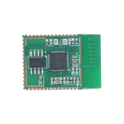
The PSH-C32 is a universal low-cost WiFi module designed by ITEAD, which adopts the highly integrated Wi-Fi chip ESP32 as MCU. Created by Espressif, the ESP32 is a new, low-cost SoC with Wi-Fi & dual-mode Bluetooth capabilities. ESP32 features at Xtensa dual-Core 32-bit Tensilica L108 MCU, operating at 160 or 240 MHz ( highest 250MHz), low-power consumption, multiple sleep modes and more. Compared to the previous generation ESP8266, ESP32 has more memory space and more I/O port for development. It is very ideal for wearable tech design.
Go shopping PSH-C32 WiFi Wireless Module(SKU: IM160913001)
Features
- Support wireless 802.11 b/g/n/e/i
- IEEE 802.11 standard security features all supported,including WFA/WPA/WPA2/WAPI
- Support WPA/WPA2 /WP2-Enterprise /WPS encryption
- Built-in TCP/IP protocol stack, support multi-way TCP Client connection
- Support Wi-Fi Direct (P2P),P2P discovery,P2P GO mode and P2P power management
- Bluetooth v4.2 complete standard, including BR/EDR and BLE
- Support standard Class-1, Class-2, Class-3 without need for external power amplifier
- Support rich Socket AT command
- Support SDK fast programming
- Support UART/GPIO data communication interface
- Built-in 32-bit MCU, can also serve as the application processor
- Supply voltage: 2.2V~3.6V, default single 3.3V power supply
Electrical Characteristics
| PARAMETER | Min | Type | Max | Unit |
|---|---|---|---|---|
| Storage Temp. | -40 | Room Temperature | 125 | ℃ |
| Working Voltage | 2.8 | 3.3 | 3.6 | V |
| I/O Vil/Vih | -0.3/0.75VIO | 0.25VIO/3.3 | V | |
| I/O Vpl/Voh | N/0.8VIO | 0.1VIO/N | V | |
| I/O Imax | 12 | mA |
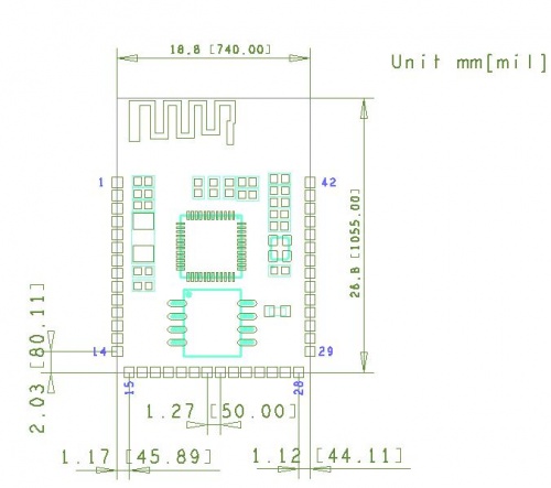
Hardware
PIN
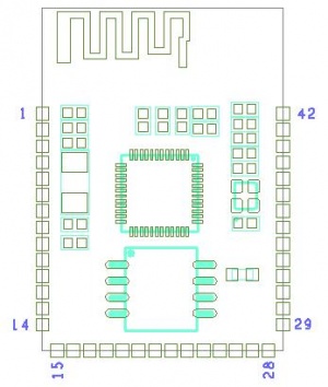
PIN MAP
| PIN | Name |
|---|---|
| 1 | CHIP_PU |
| 2 | SENSOR_VP |
| 3 | SENSOR_CAPP |
| 4 | SENSOR_CAPN |
| 5 | SENSOR_VN |
| 6 | VDET_1 |
| 7 | VDET_2 |
| 8 | 32K_XP |
| 9 | 32K_XN |
| 10 | GPIO25 |
| 11 | GPIO26 |
| 12 | GPIO27 |
| 13 | GND |
| 14 | GND |
| 15 | MTMS |
| 16 | MTDI |
| 17 | MTCK |
| 18 | MTDO |
| 19 | GPIO2 |
| 20 | GPIO0 |
| 21 | GPIO4 |
| 22 | GPIO16 |
| 23 | GPIO17 |
| 24 | NC |
| 25 | NC |
| 26 | NC |
| 27 | NC |
| 28 | NC |
| 29 | NC |
| 30 | GPIO5 |
| 31 | GPIO18 |
| 32 | GPIO23 |
| 33 | GPIO19 |
| 34 | GPIO22 |
| 35 | U0RXD |
| 36 | U0TXD |
| 37 | GPIO21 |
| 38 | VCC |
| 39 | VCC |
| 40 | GND |
| 41 | GND |
| 42 | GND |
Strapping Pins
There are totally 6 Strapping pins in ESP32:
- MTDI/GPIO12: internal pull-down
- GPIO0: internal pull-up
- GPIO2: internal pull-down
- GPIO4: internal pull-down
- MTDO/GPIO15: internal pull-up
- GPIO5: internal pull-up
Pin Mode
| Mode | GPIO0 | GPIO2 |
|---|---|---|
| UART Download | Low | Low |
| Flash Boot | High | / |
Confirm Function: After power up, level of 18 IO ports will auto-flip, the frequency is 1s:
               GPIO0,GPIO2,
               GPIO4,GPIO5,
               GPIO12,GPIO13,
               GPIO14,GPIO15,
               GPIO16,GPIO17,
               GPIO18,GPIO19,
               GPIO21,GPIO22,
               GPIO23,GPIO25,
               GPIO26,GPIO27
Connect the serial port, open the serial assistant, when the baudrate is 115200, it will display current number of SSID that can be searched and the first SSID name can be searched.
 Notice

