Difference between revisions of "Iteaduino Tiny"
m (→Features) |
m (→Useful Link) |
||
| (One intermediate revision by the same user not shown) | |||
| Line 11: | Line 11: | ||
* 4 I/O Pins | * 4 I/O Pins | ||
* 8k Flash Memory (about 6k after bootloader) | * 8k Flash Memory (about 6k after bootloader) | ||
| − | * I2C and SPI (vis USI) Note:also supports for serial port communication | + | * I2C and SPI (vis USI) Note:also supports for serial port communication |
* PWM on 3 pins (more possible with Software PWM) | * PWM on 3 pins (more possible with Software PWM) | ||
* ADC on 4 pins | * ADC on 4 pins | ||
| Line 121: | Line 121: | ||
http://www.ernstc.dk/arduino/tinycom.html | http://www.ernstc.dk/arduino/tinycom.html | ||
| + | |||
| + | http://playground.arduino.cc/Code/USIi2c | ||
Latest revision as of 02:42, 28 June 2016
Overview
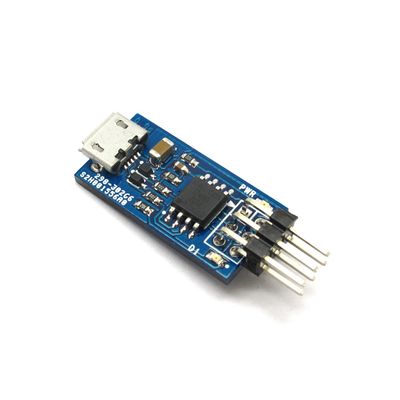
Iteaduino Tiny is a mini development board based on Attiny85-20 master, which is cheap, compact and easy to use with low power consumption. The mainboard is a derivative board with reference to digispark design, and it supports use of specific Arduino IDE and uses Arduino syntax for programming which is quite convenient.
Go shopping Iteaduino Tiny (SKU:IM130615003)
Features
- Support for the Arduino IDE 1.0+ (Windows)
- Power via USB
- Built-in USB
- 4 I/O Pins
- 8k Flash Memory (about 6k after bootloader)
- I2C and SPI (vis USI) Note:also supports for serial port communication
- PWM on 3 pins (more possible with Software PWM)
- ADC on 4 pins
- Power LED and Test/Status LED
Spec
| Microcontroller | ATtiny85-20 |
| Operating Voltage | 5V |
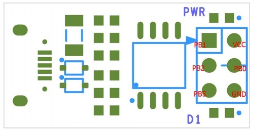
| Digital IO pins | PB0, PB1, PB2, PB5 |
| Analog Input pins(ADC) | PB2 |
| Indicator | D1(PB1), PWR |
| DC Output current on per IO lines | 40mA |
| Flash Memory | 8 KB of which 2 KB used by bootloader |
| SRAM | 512B |
| EEPROM | 512B |
| Clock frequency | 16 MHz |
| Dimension | 24.89X12.7X1.6mm |
Hardware
Pin Map
| ISP Pin | Index of Digital Pin | Name of Attiny85 |
| MISO | D1 | PB1(MISO/DO/AIN1/OC0B/OC1A/PCINT1) |
| VCC | - | - |
| SCK | D2 | PB2(SCK/USCK/SCL/ADC1/T0/INT0/PCINT2) |
| MOSI | D0 | PB0(MOSI/DI/SDA/AIN0/OC0A/OC1A/AREF/PCINT0) |
| RST# | D5 | PB5(PCINT5/RESET/ADC0/dW) |
| GND | - | - |
Software
Let’s take Windows7 operating system as an example, before we use Iteaduino Tiny, we need to install driver for it. First, download the modified Arduino IDE offered by Digispart in the following address: http://sourceforge.net/projects/digistump/files/.
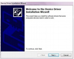
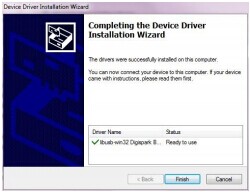
We included Digispart USB driver files in the document, so we can execute the driver file (DigisparkArduino-Win32->DigisparkWindowsDriver->InstallDriver.exe)to install the driver in the system. Keep clicking "Next" till installation of the USB device is completed.
When Iteaduino Tiny is connected to a computer via USB at the first time, the system will find the new device and display installing Digispart bootloader,
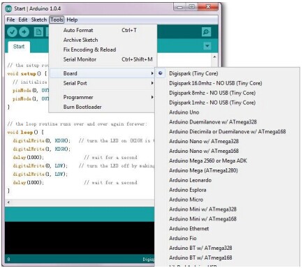
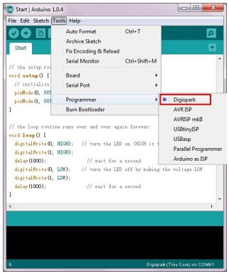
Next, you can run DigisparkArduino-Win32Digispark-Arduino-1.0.4arduino.exe, open the modified Arduino IDE, where we can write and compile our codes. During downloading, you need to select the board type, browse and select Tool> Board> Digispark (Tiny Core) in sequence. Then choose Tools> programmer> Digispark.
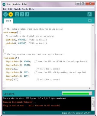
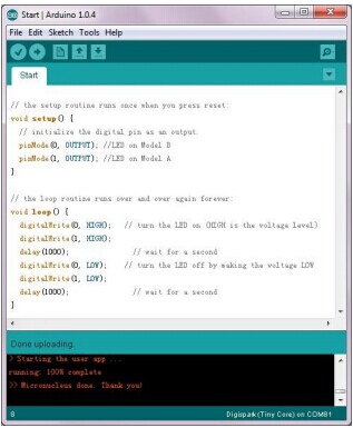
Because there is no reset pin on Tinny85, before pressing the "upload" button to download codes onto Iteaduino Tiny, you need to unplug the USB cable on Iteaduino Tiny first to disconnect the USB connection. Then, press the "upload" button, after ‘Plug in device now…’ is displayed on IDE window, reconnect the USB cable, and then IDE will download the compiled data onto Iteaduino Tiny. For details about operating procedures, please refer to user manual for Iteaduino Tiny.
Download
Useful Link
Useful links for your reference:
http://www.txoof.com/2013/04/reading-serial-data-from-attiny85.html
 Notice