Difference between revisions of "W5100 Ethernet Shield V1.1"
m (→Specifications) |
m (→Overview) |
||
| (10 intermediate revisions by the same user not shown) | |||
| Line 1: | Line 1: | ||
==Overview== | ==Overview== | ||
| + | |||
| + | [[File:IM151104001 (5).jpg|thumb|400px|right]] | ||
W5100 Ethernet shield V1.1 is a WIZnet W5100 breakout board with POE and Micro-SD designed for Arduino platform. 5V/3.3V compatible operation voltage level makes it compatible with Arduino boards, leafmaple, and other Arduino compatible boards except Mega boards. | W5100 Ethernet shield V1.1 is a WIZnet W5100 breakout board with POE and Micro-SD designed for Arduino platform. 5V/3.3V compatible operation voltage level makes it compatible with Arduino boards, leafmaple, and other Arduino compatible boards except Mega boards. | ||
'''Note:''' the POE of W5100 shield V1.1 is dummy POE. Because in the 100M ethernet wire, 7/8 pins are not used. It will be connected to VIN pin of arduino board directly. | '''Note:''' the POE of W5100 shield V1.1 is dummy POE. Because in the 100M ethernet wire, 7/8 pins are not used. It will be connected to VIN pin of arduino board directly. | ||
| + | |||
| + | Go shopping [http://www.itead.cc/w5100-ethernet-shield-v1-1.html W5100 Ethernet Shield V1.1 (SKU:IM151104001)] | ||
==Features== | ==Features== | ||
| Line 25: | Line 29: | ||
==Electrical Characteristics== | ==Electrical Characteristics== | ||
| + | {| class="wikitable" | ||
| + | |- | ||
| + | | align="center" style="background:#f0f0f0;"|'''Specification''' | ||
| + | | align="center" style="background:#f0f0f0;"|'''Min.''' | ||
| + | | align="center" style="background:#f0f0f0;"|'''Typ.''' | ||
| + | | align="center" style="background:#f0f0f0;"|'''Max''' | ||
| + | | align="center" style="background:#f0f0f0;"|'''Unit''' | ||
| + | |- | ||
| + | | Power voltage||3||-||5.5||VDC | ||
| + | |- | ||
| + | | Input Voltage VH:||3||-||5.5||V | ||
| + | |- | ||
| + | | Input Voltage VL:||-0.3||-||0.5||V | ||
| + | |- | ||
| + | | Current Consumption||-||-||100||mA | ||
| + | |- | ||
| + | |} | ||
| + | |||
==Hardware== | ==Hardware== | ||
| + | [[File:IM151104001 - W5100 Ethernet Shield V1.1 - view.png|500px]] | ||
| + | |||
| + | {| class="wikitable" | ||
| + | |- | ||
| + | | align="center" style="background:#f0f0f0;"|'''Arduino PIN''' | ||
| + | | align="center" style="background:#f0f0f0;"|'''Description''' | ||
| + | |- | ||
| + | | D4||SD_CS | ||
| + | |- | ||
| + | | D9||W5100_RST | ||
| + | |- | ||
| + | | D10||W5100_CS | ||
| + | |- | ||
| + | |} | ||
| + | |||
| + | *Note: D9 is the software reset pin for W5100. Active High. Send a high voltage pulse on D9 will reset W5100. | ||
| + | |||
==Installation== | ==Installation== | ||
| + | When install W5100 Ethernet shield V1.1 to Iteaduino, please check the operation voltage level of development board. If the voltage is 3.3V (IFLAT32,Leafmaple), set the Operation Level Setting switch to 3.3V. If the voltage is 5V(Arduino), set the Operation Level Setting switch to 5V. | ||
| + | |||
| + | Iteaduino communicates with both the W5100 and SD card using the SPI bus. This is on digital pins 11, 12, and 13 on the UNO/Duemilanove and pins 50, 51, and 52 on the Mega. On both boards, pin 10 is used to select the W5100 and pin 4 for the SD card. These pins cannot be used for general I/O. On the Mega, the hardware SS pin, 53, is not used to select either the W5100 or the SD card, but it must be kept as an output. | ||
| + | |||
| + | Note that because the W5100 and SD card share the SPI bus, only one can be active at a time. If you are using both peripherals in your program, this should be taken care of by the corresponding libraries. If you're not using one of the peripherals in your program, however, you'll need to explicitly deselect it. To do this with the SD card, set pin 4 as an output and write a high to it. For the W5100, set digital pin 10 as a high output. | ||
| + | |||
==Indicator LED== | ==Indicator LED== | ||
| + | The shield contains a number of informational LEDs: | ||
| + | *LNK: indicates the presence of a network link and flashes when the shield transmits or receives data | ||
| + | *FEX: indicates that the network connection is full duplex | ||
| + | *SPD: indicates the presence of a 100 Mb/s network connection (as opposed to 10 Mb/s) | ||
| + | *RX: flashes when the shield receives data | ||
| + | *TX: flashes when the shield sends data | ||
| + | *COL: flashes when network collisions are detected | ||
| + | |||
==Download== | ==Download== | ||
| + | [[:File:IM151104001 - W5100 Ethernet Shield V1.1 - dimension.pdf|Datasheet of W5100 Ethernet Shield V1.1]] | ||
| + | |||
| + | [[:File:IM151104001 - W5100 Ethernet Shield V1.1 - schematic.pdf|Schematic of W5100 Ethernet Shield V1.1]] | ||
| + | |||
| + | ==Useful Links== | ||
| + | 【From Phillip Stevens】 | ||
| + | |||
| + | Prepared an integrated W5500 / W5200 / W5100 code here. | ||
| + | *One socket.h/.c interface. | ||
| + | *Based on freeRTOS for AVR (Arduino). | ||
| + | |||
| + | *freeRTOS/lib_iinchip | ||
| + | *freeRTOS/lib_inet | ||
| + | |||
| + | *https://sourceforge.net/projects/avrfreertos/ | ||
Latest revision as of 03:29, 19 November 2015
Contents
[hide]Overview
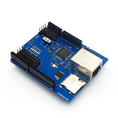
W5100 Ethernet shield V1.1 is a WIZnet W5100 breakout board with POE and Micro-SD designed for Arduino platform. 5V/3.3V compatible operation voltage level makes it compatible with Arduino boards, leafmaple, and other Arduino compatible boards except Mega boards.
Note: the POE of W5100 shield V1.1 is dummy POE. Because in the 100M ethernet wire, 7/8 pins are not used. It will be connected to VIN pin of arduino board directly.
Go shopping W5100 Ethernet Shield V1.1 (SKU:IM151104001)
Features
- With Micro SD interface
- 5V/3.3V double operational voltage level
- 10Mb/100Mb Ethernet socket with POE
- All electronic brick interface are broken out
Specifications
| PCB size | 68.6mm X 55.9mm X 1.6mm |
| Indicators | TX,RX,COL,FEX,SPD,LNK |
| Power supply | 5V |
| Communication Protocol | SPI |
Electrical Characteristics
| Specification | Min. | Typ. | Max | Unit |
| Power voltage | 3 | - | 5.5 | VDC |
| Input Voltage VH: | 3 | - | 5.5 | V |
| Input Voltage VL: | -0.3 | - | 0.5 | V |
| Current Consumption | - | - | 100 | mA |
Hardware
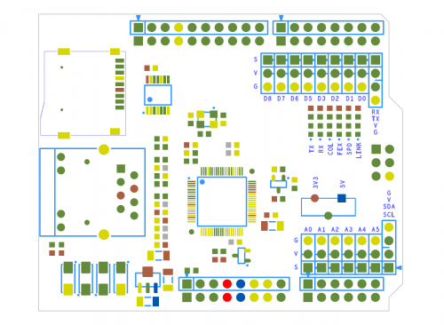
| Arduino PIN | Description |
| D4 | SD_CS |
| D9 | W5100_RST |
| D10 | W5100_CS |
- Note: D9 is the software reset pin for W5100. Active High. Send a high voltage pulse on D9 will reset W5100.
Installation
When install W5100 Ethernet shield V1.1 to Iteaduino, please check the operation voltage level of development board. If the voltage is 3.3V (IFLAT32,Leafmaple), set the Operation Level Setting switch to 3.3V. If the voltage is 5V(Arduino), set the Operation Level Setting switch to 5V.
Iteaduino communicates with both the W5100 and SD card using the SPI bus. This is on digital pins 11, 12, and 13 on the UNO/Duemilanove and pins 50, 51, and 52 on the Mega. On both boards, pin 10 is used to select the W5100 and pin 4 for the SD card. These pins cannot be used for general I/O. On the Mega, the hardware SS pin, 53, is not used to select either the W5100 or the SD card, but it must be kept as an output.
Note that because the W5100 and SD card share the SPI bus, only one can be active at a time. If you are using both peripherals in your program, this should be taken care of by the corresponding libraries. If you're not using one of the peripherals in your program, however, you'll need to explicitly deselect it. To do this with the SD card, set pin 4 as an output and write a high to it. For the W5100, set digital pin 10 as a high output.
Indicator LED
The shield contains a number of informational LEDs:
- LNK: indicates the presence of a network link and flashes when the shield transmits or receives data
- FEX: indicates that the network connection is full duplex
- SPD: indicates the presence of a 100 Mb/s network connection (as opposed to 10 Mb/s)
- RX: flashes when the shield receives data
- TX: flashes when the shield sends data
- COL: flashes when network collisions are detected
Download
Datasheet of W5100 Ethernet Shield V1.1
Schematic of W5100 Ethernet Shield V1.1
Useful Links
【From Phillip Stevens】
Prepared an integrated W5500 / W5200 / W5100 code here.
- One socket.h/.c interface.
- Based on freeRTOS for AVR (Arduino).
- freeRTOS/lib_iinchip
- freeRTOS/lib_inet
 Notice
