Difference between revisions of "SIM900/SIM900A GSM/GPRS Minimum System Module"
m (→Download) |
m (→Download) |
||
| Line 123: | Line 123: | ||
[https://github.com/itead/ITEADLIB_Arduino_SIMCom GSM GPRS GPS Bluetooth for SIM800/808/900/908 Library] | [https://github.com/itead/ITEADLIB_Arduino_SIMCom GSM GPRS GPS Bluetooth for SIM800/808/900/908 Library] | ||
| + | |||
| + | [[:File:SIM900_MMS_AT Command Manual_V1.04.pdf]] | ||
==Useful Links== | ==Useful Links== | ||
Latest revision as of 09:36, 23 August 2016
Contents
Overview
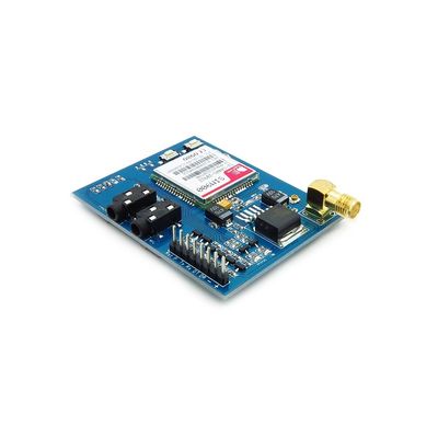
GPRS module is a breakout board and minimum system of SIM900 Quad-band/SIM900A Dual-band GSM/GPRS module. It can communicate with controllers via AT commands (GSM 07.07 ,07.05 and SIMCOM enhanced AT Commands). This module supports software power on and reset.
Go shopping SIM900/SIM900A GSM/GPRS Minimum System Module (IM120525010)
Features
- Quad-Band 850/ 900/ 1800/ 1900 MHz
- Dual-Band 900/ 1900 MHz
- GPRS multi-slot class 10/8GPRS mobile station class B
- Compliant to GSM phase 2/2+Class 4 (2 W @850/ 900 MHz)
- Class 1 (1 W @ 1800/1900MHz)
- Control via AT commands (GSM 07.07 ,07.05 and SIMCOM enhanced AT Commands)
- Low power consumption: 1.5mA(sleep mode)
- Operation temperature: -40°C to +85 °C

Specifications
| PCB size | 71.4mm X 66.0mm X1.6mm |
| Indicators | PWR, status LED, net LED |
| Power supply | 5V |
| Communication Protocol | UART |
| RoHS | Yes |
Electrical Characteristics
| Parameter | Min. | Typical | Max. | Unit |
| Power voltage (Vsupply) | 4.5 | 5.5 | VDC | |
| Input voltage VH | 0.7VCC | 5.5 | V | |
| Input voltage VL | -0.3 | 0 | 0.3VCC | V |
| Current Consumption (pulse) | - | 2000 | mA | |
| Current Consumption (continuous) | 500 | mA | ||
| Baud rate | 115200 | bps |
Hardware
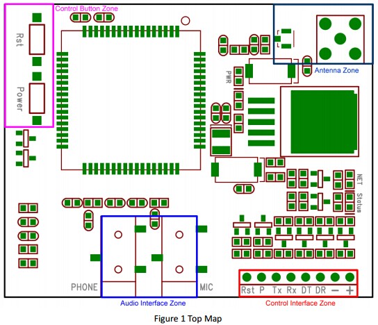
| Interface | Pin | Description |
| Rst | 1 | Reset the SIM900 module |
| P | 2 | Power switch pin of SIM900 module |
| Tx | 3 | UART data output |
| Rx | 4 | UART data in |
| DT | 5 | Debug UART data output |
| DR | 6 | Debug UART data input |
| - | 7 | GND |
| + | 8 | VCC |
Installation
Power on GPRS module
User can power on the GPRS module by pulling down the PWR button or the P pin of control interface for at least 1 second and release. This pin is already pulled up to 3V in the module internal, so external pull up is not necessary. When power on procedure is completed, GPRS module will send following URC to indicate that the module is ready to operate at fixed baud rate.
Indicator LED and Buttons:
NETSTATUS: The status of the NETSTATUS LED is listed in following table:
| Status | Description |
| Off | SIM900 is not running 64ms On/800ms |
| Off | SIM900 not registered the network |
| 64ms On/3000ms Off | SIM900 registered to the network |
| 64ms On/300ms Off | GPRS communication is established |
STATUS: Power status of SIM900.
PWR: Power status of GPRS module.
PWR: After the GPRS module power on, you need to press the POWER button for a moment to power on the SIM900 module.
RESET: Reset the SIM900 module.
Note
In some countries where dual band exists, we recommend to use SIM900A to reduce costs. For the country list, please click here.
Download
GSM GPRS GPS Bluetooth for SIM800/808/900/908 Library
File:SIM900_MMS_AT Command Manual_V1.04.pdf
Useful Links
MarcoMartines' GitHub Page <GSM/GPRS & GPS Shield Library for modules using SIM900/SIM908>
SIM900 firmware upgrade, please refer to the following link:
 Notice
