Difference between revisions of "ITDB02-2.4S/zh-cn"
From ITEAD Wiki
(Created page with "==概述== right ITDB02-2.4S 是一个2.4inch SPI接口的TFT LCD模块,分辨率为320X240,262K种颜色。LCD模块的控制...") |
(Created page with "==相关链接== https://github.com/adafruit/Adafruit_ILI9340") |
||
| (12 intermediate revisions by the same user not shown) | |||
| Line 3: | Line 3: | ||
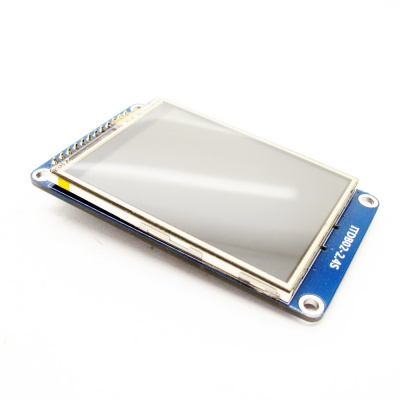
[[ITDB02-2.4S]] 是一个2.4inch SPI接口的TFT LCD模块,分辨率为320X240,262K种颜色。LCD模块的控制芯片为ILI9341V,它的接口是SPI的,需要6根线(SCK,MISO,MOSI,CS,D/C,RST)来控制。而且,这个模块还包含了micro SD卡接口,带触摸功能。 | [[ITDB02-2.4S]] 是一个2.4inch SPI接口的TFT LCD模块,分辨率为320X240,262K种颜色。LCD模块的控制芯片为ILI9341V,它的接口是SPI的,需要6根线(SCK,MISO,MOSI,CS,D/C,RST)来控制。而且,这个模块还包含了micro SD卡接口,带触摸功能。 | ||
| − | + | 购买 [http://imall.iteadstudio.com/itdb02-2-4s.html ITDB02-2.4S (SKU:IM140714002)] | |
| − | == | + | ==特点== |
| − | * | + | *兼容3.3/5V操作电平 |
| − | * | + | *自带micro SD卡接口 |
| − | * | + | *支持用IO口或PWM来控制背光 |
| − | * | + | *触摸屏 |
| − | == | + | ==规格== |
{| border="1" | {| border="1" | ||
| − | | | + | | PCB尺寸||44mm X 74mm X 1.6mm |
|- | |- | ||
| − | | | + | | 电源||5V DC |
|- | |- | ||
| − | | | + | | 驱动IC||ILI9341V |
|- | |- | ||
| − | | | + | | 分辨率||320*240 |
|- | |- | ||
|} | |} | ||
| − | == | + | ==电气特性== |
{| class="wikitable" | {| class="wikitable" | ||
|- | |- | ||
| − | | align="center" style="background:#f0f0f0;"|''' | + | | align="center" style="background:#f0f0f0;"|'''参数''' |
| − | | align="center" style="background:#f0f0f0;"|''' | + | | align="center" style="background:#f0f0f0;"|'''最小值''' |
| − | | align="center" style="background:#f0f0f0;"|''' | + | | align="center" style="background:#f0f0f0;"|'''经典值''' |
| − | | align="center" style="background:#f0f0f0;"|''' | + | | align="center" style="background:#f0f0f0;"|'''最大值''' |
| − | | align="center" style="background:#f0f0f0;"|''' | + | | align="center" style="background:#f0f0f0;"|'''单位''' |
|- | |- | ||
| − | | | + | | 电源||4.5||5||5.5||VDC |
|- | |- | ||
| − | | | + | | 最高输入电压 (Target Voltage = 3.3V)||3||3.3||3.6||V |
|- | |- | ||
| − | | | + | | 最高输入电压 (Target Voltage = 5V)||4.5||5||5.5||V |
|- | |- | ||
| − | | | + | | 最低输入电压||-0.3||0||0.5||V |
|- | |- | ||
| − | | | + | | 电流||-||40||80||mA |
|} | |} | ||
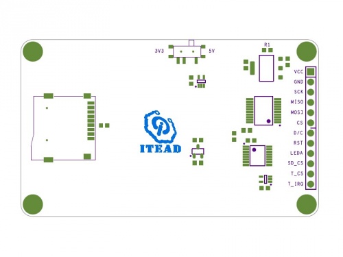
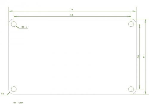
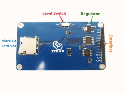
| − | == | + | ==硬件图== |
[[File:IM140714002pic1.jpg|500px]] | [[File:IM140714002pic1.jpg|500px]] | ||
[[File:IM140714002pic2.jpg|500px]] | [[File:IM140714002pic2.jpg|500px]] | ||
| Line 51: | Line 51: | ||
{| class="wikitable" | {| class="wikitable" | ||
|- | |- | ||
| − | | align="center" style="background:#f0f0f0;"|''' | + | | align="center" style="background:#f0f0f0;"|'''引脚''' |
| − | | align="center" style="background:#f0f0f0;"|''' | + | | align="center" style="background:#f0f0f0;"|'''类型*''' |
| − | | align="center" style="background:#f0f0f0;"|''' | + | | align="center" style="background:#f0f0f0;"|'''描述''' |
|- | |- | ||
| VCC||P||5V Power supply pin | | VCC||P||5V Power supply pin | ||
| Line 80: | Line 80: | ||
|- | |- | ||
|} | |} | ||
| − | * | + | *类型: P:电源; G:地; I:输入; O:输出. |
| − | *LEDA: | + | *LEDA: 当LEDA设置为高电平,背光会亮;当LEDA设置为低电平,背光会熄灭。 |
| − | == | + | ==使用指南== |
| − | <big>'''1. | + | <big>'''1.触摸功能'''</big> |
| − | * | + | *把 '''2_4_spi_touch.ino''' 烧写进 UNO 主板 |
::[[:File:2_4_spi_touch.zip]] | ::[[:File:2_4_spi_touch.zip]] | ||
| − | * | + | *然后按照以下的接线方式连接UNO和[[ITDB02-2.4S]]模块: |
{| class="wikitable wikitable-indent" | {| class="wikitable wikitable-indent" | ||
|- | |- | ||
| Line 119: | Line 119: | ||
|- | |- | ||
|} | |} | ||
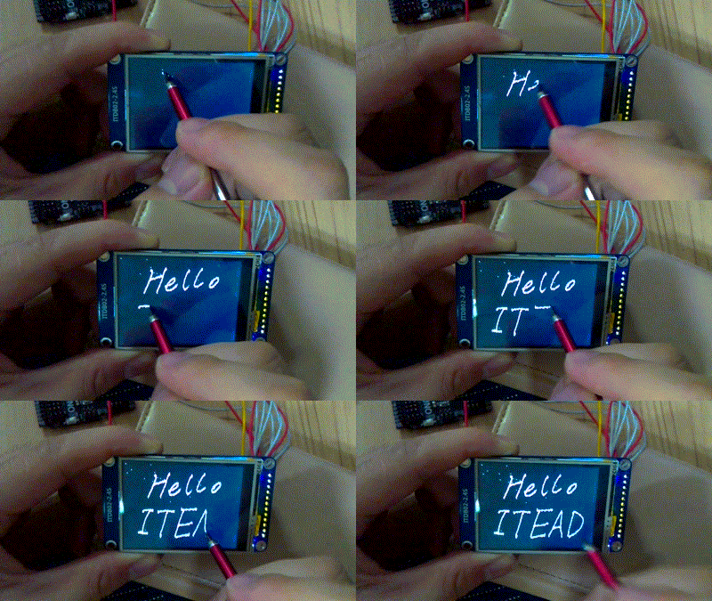
| − | * | + | *插上电源后,可以在屏幕上随意画出任何图案或线条。 |
[[File:IM140714002in2.gif|400px]] | [[File:IM140714002in2.gif|400px]] | ||
| − | <big>'''2. | + | <big>'''2.能显示micro SD中的图片'''</big> |
| − | * | + | *第一:下载并安装Adafruit_ILI9340的库:https://github.com/adafruit/Adafruit_ILI9340 |
| − | * | + | *第二,把Adafruit_ILI9340\examples\spitftbitmap目录下的woof.bmp图片拷贝到micro SD卡中。然后把SD卡插到[[ITDB02-2.4S]]模块的micro SD卡座上。 |
| − | * | + | *第三,用UNO烧写程序。用arduino IDE打开Adafruit_ILI9340中spitftbitmap的例子。然后按照以下的接线方式连接UNO和[[ITDB02-2.4S]]模块: |
| − | + | ||
{| class="wikitable wikitable-indent" | {| class="wikitable wikitable-indent" | ||
|- | |- | ||
| Line 153: | Line 152: | ||
|- | |- | ||
|} | |} | ||
| − | * | + | *插上电源,屏幕上会显示一只狗的图片。 |
| − | == | + | ==文件下载== |
| − | + | TFT LCD模块说明书--[[:File:H24TM84A-spec.pdf]] | |
| − | + | 原理图--[[:File:IM140714002-ITDB02-2.4S-schematic.pdf]] | |
| − | == | + | ==相关链接== |
https://github.com/adafruit/Adafruit_ILI9340 | https://github.com/adafruit/Adafruit_ILI9340 | ||
Latest revision as of 01:52, 9 August 2014
概述
ITDB02-2.4S 是一个2.4inch SPI接口的TFT LCD模块,分辨率为320X240,262K种颜色。LCD模块的控制芯片为ILI9341V,它的接口是SPI的,需要6根线(SCK,MISO,MOSI,CS,D/C,RST)来控制。而且,这个模块还包含了micro SD卡接口,带触摸功能。
购买 ITDB02-2.4S (SKU:IM140714002)
特点
- 兼容3.3/5V操作电平
- 自带micro SD卡接口
- 支持用IO口或PWM来控制背光
- 触摸屏
规格
| PCB尺寸 | 44mm X 74mm X 1.6mm |
| 电源 | 5V DC |
| 驱动IC | ILI9341V |
| 分辨率 | 320*240 |
电气特性
| 参数 | 最小值 | 经典值 | 最大值 | 单位 |
| 电源 | 4.5 | 5 | 5.5 | VDC |
| 最高输入电压 (Target Voltage = 3.3V) | 3 | 3.3 | 3.6 | V |
| 最高输入电压 (Target Voltage = 5V) | 4.5 | 5 | 5.5 | V |
| 最低输入电压 | -0.3 | 0 | 0.5 | V |
| 电流 | - | 40 | 80 | mA |
硬件图
Pin Map
| 引脚 | 类型* | 描述 |
| VCC | P | 5V Power supply pin |
| GND | G | Ground |
| SCK | I | SPI SCK |
| MISO | O | SPI MISO |
| MOSI | I | SPI MOSI |
| CS | I | Chip Select for TFT |
| D/C | I | Command or parameter select |
| RST | I | RESET signal for TFT |
| LEDA* | I | Backlight control pin |
| SD_CS | I | Chip Select for SD |
| T_CS | I | Chip Select for touch function |
| T_IRQ | O | Interrupt output for touch |
- 类型: P:电源; G:地; I:输入; O:输出.
- LEDA: 当LEDA设置为高电平,背光会亮;当LEDA设置为低电平,背光会熄灭。
使用指南
1.触摸功能
- 把 2_4_spi_touch.ino 烧写进 UNO 主板
- 然后按照以下的接线方式连接UNO和ITDB02-2.4S模块:
| 2.4S pins | UNO pins |
| VCC | 5V |
| GND | GND |
| SCK | D13 |
| MISO | D12 |
| MOSI | D11 |
| CS | D10 |
| D/C | D9 |
| RST | D8 |
| LEDA | 5V/3V3 |
| SD_CS | D4 |
| T_CS | D2 |
| T_IRQ | D3 |
- 插上电源后,可以在屏幕上随意画出任何图案或线条。
2.能显示micro SD中的图片
- 第一:下载并安装Adafruit_ILI9340的库:https://github.com/adafruit/Adafruit_ILI9340
- 第二,把Adafruit_ILI9340\examples\spitftbitmap目录下的woof.bmp图片拷贝到micro SD卡中。然后把SD卡插到ITDB02-2.4S模块的micro SD卡座上。
- 第三,用UNO烧写程序。用arduino IDE打开Adafruit_ILI9340中spitftbitmap的例子。然后按照以下的接线方式连接UNO和ITDB02-2.4S模块:
| 2.4S pins | UNO pins |
| VCC | 5V |
| GND | GND |
| SCK | D13 |
| MISO | D12 |
| MOSI | D11 |
| CS | D10 |
| D/C | D9 |
| RST | D8 |
| LEDA | 5V/3V3 |
| SD_CS | D4 |
- 插上电源,屏幕上会显示一只狗的图片。
文件下载
TFT LCD模块说明书--File:H24TM84A-spec.pdf
原理图--File:IM140714002-ITDB02-2.4S-schematic.pdf
 Notice