Difference between revisions of "ITDB02-5.0"
From ITEAD Wiki
m (→Hardware) |
m (→Overview) |
||
| (9 intermediate revisions by the same user not shown) | |||
| Line 1: | Line 1: | ||
==Overview== | ==Overview== | ||
| − | [[File: | + | [[File:IM120419008_3.jpg|thumb|400px|right]] |
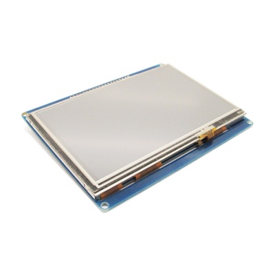
| − | ITDB02-5.0 module is 5.0" TFT LCD with 65K color 800 x 480 resolutions. The controller of this LCD module is SSD1963 | + | ITDB02-5.0 display module is a 5.0" TFT LCD with 65K color 800 x 480 resolutions. The controller of this LCD module is SSD1963. It supports 16bit data interface with control interface of four wires. Moreover, this module contains the touch screen and SD card socket. |
ITDB02-5.0 is supported by UTFT Library. | ITDB02-5.0 is supported by UTFT Library. | ||
| Line 28: | Line 28: | ||
==Hardware== | ==Hardware== | ||
| − | + | [[File:IM120419008pic1.jpg|500px]] | |
| + | [[File:IM120419008pic2.jpg|500px]] | ||
| + | [[File:IM120419008pic3.jpg|500px]] | ||
| − | + | ==Pin Map== | |
{| class="wikitable" | {| class="wikitable" | ||
| Line 67: | Line 69: | ||
|- | |- | ||
| CS||I||Chip Selection,Low level active | | CS||I||Chip Selection,Low level active | ||
| + | |- | ||
| + | | NC||-||No connection | ||
| + | |- | ||
| + | | RST||I||Reset Pin | ||
|- | |- | ||
| NC||-||No connection | | NC||-||No connection | ||
| Line 114: | Line 120: | ||
| NC||-||No connection | | NC||-||No connection | ||
|} | |} | ||
| + | |||
| + | ==Download== | ||
| + | Schematic--[[:File:IM120419008-ITDB02-5_0-schematic.pdf]] | ||
==Useful Links== | ==Useful Links== | ||
| − | [http:// | + | [http://www.rinkydinkelectronics.com/library.php?id=51 by Henning Karlsen <UTFT library>] |
Latest revision as of 06:31, 12 January 2017
Overview
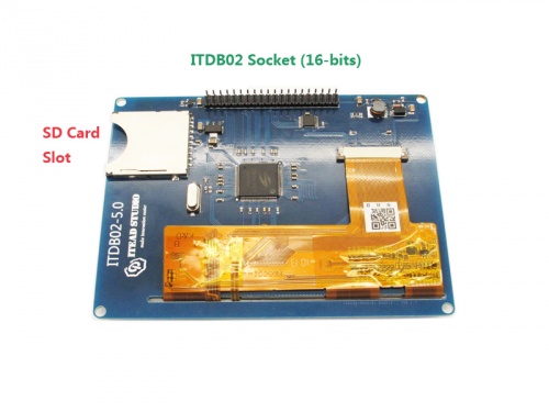
ITDB02-5.0 display module is a 5.0" TFT LCD with 65K color 800 x 480 resolutions. The controller of this LCD module is SSD1963. It supports 16bit data interface with control interface of four wires. Moreover, this module contains the touch screen and SD card socket.
ITDB02-5.0 is supported by UTFT Library.
Go shopping ITDB02-5.0 (IM120419008)
Specifications
| Driver IC | SSD1963 |
| Backlight | |
| Power supply | 3.3V |
| Touch Panel | Y |
| Touch IC | XPT2046 |
| Resolution | 800*480 |
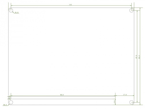
| Size | 90mm*115mm |
Hardware
Pin Map
| Pin | Type* | Description |
| GND | G | Ground |
| VCC | P | 5V Power Supply pin |
| NC | - | No connection |
| RS | I | Data/Command selection |
| WR | I | Write signal enable, low active |
| RD | I | Read signal enable, low active |
| DB8 | I | Data Bus |
| DB9 | I | Data Bus |
| DB10 | I | Data Bus |
| DB11 | I | Data Bus |
| DB12 | I | Data Bus |
| DB13 | I | Data Bus |
| DB14 | I | Data Bus |
| DB15 | I | Data Bus |
| CS | I | Chip Selection,Low level active |
| NC | - | No connection |
| RST | I | Reset Pin |
| NC | - | No connection |
| LED | P | Backlight(3.3V) |
| NC | - | No connection |
| DB0 | I | Data Bus |
| DB1 | I | Data Bus |
| DB2 | I | Data Bus |
| DB3 | I | Data Bus |
| DB4 | I | Data Bus |
| DB5 | I | Data Bus |
| DB6 | I | Data Bus |
| DB7 | I | Data Bus |
| T_CLK | I | Touch clock |
| T_CS | I | Touch chip selection |
| T_DIN | I | Touch data input |
| T_BUSY | O | Touch status |
| T_DOUT | O | Touch data output |
| T_IRQ | O | Touch interrupt |
| SD_SO | O | SD MISO |
| SD_SCK | I | SD SCK |
| SD_SI | I | SD MOSI |
| SD_NSS | I | SD NSS |
| NC | - | No connection |
| NC | - | No connection |
Download
Schematic--File:IM120419008-ITDB02-5_0-schematic.pdf
 Notice


