Difference between revisions of "Iteaduino BT"
(→Spec) |
m (→Communicate mode set jumper) |
||
| (17 intermediate revisions by 2 users not shown) | |||
| Line 1: | Line 1: | ||
==Overview== | ==Overview== | ||
| + | |||
| + | [[File:IteaduinoBT3.jpg|thumb|400px|right]] | ||
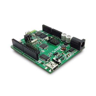
Iteaduino-BT is an Arduino compatible board with a master/slave Bluetooth Module HC-05. It based on Arduino UNO/Duemilanove, 100% compatible with its existing program and shields, but with the bluetooth wireless funcion. The power consumption is about 50% of the original Arduino boards. | Iteaduino-BT is an Arduino compatible board with a master/slave Bluetooth Module HC-05. It based on Arduino UNO/Duemilanove, 100% compatible with its existing program and shields, but with the bluetooth wireless funcion. The power consumption is about 50% of the original Arduino boards. | ||
| + | |||
| + | Go shopping [http://imall.iteadstudio.com/im120411006.html Iteaduino BT (SKU:IM120411006)] | ||
==Features== | ==Features== | ||
| − | Design for Bluetooth communication | + | * Design for Bluetooth communication |
| − | Compatible with Arduino UNO/Duemilanove pins, holes and dimensions | + | * Compatible with Arduino UNO/Duemilanove pins, holes and dimensions |
| − | Wide range external input from 7~23V DC | + | * Wide range external input from 7~23V DC |
| − | Pins out for Sensor and Servo | + | * Pins out for Sensor and Servo |
| − | 3.3V/5V Operating Voltage selection | + | * 3.3V/5V Operating Voltage selection |
| + | |||
| + | ==Spec== | ||
| + | {| border="1" | ||
| + | |||
| + | |- | ||
| + | | Microcontroller | ||
| + | | ATMega328P | ||
| + | |||
| + | |- | ||
| + | | PCB size | ||
| + | | 10mm X 82mm X 1.6mm | ||
| + | |- | ||
| + | | Indicators | ||
| + | | Power,TX,RX,D13,LED1,LED2 | ||
| + | |- | ||
| + | | Power supply(recommended) | ||
| + | | 7-23V DC | ||
| + | |- | ||
| + | | Power supply(limits) | ||
| + | | 23 VDC (max) | ||
| + | |- | ||
| + | | Communication Protocol | ||
| + | | UART,SPI,IIC | ||
| + | |- | ||
| + | | Clock Speed | ||
| + | | 16MHz | ||
| + | |- | ||
| + | | RoHS | ||
| + | | Yes | ||
| + | |} | ||
| + | |||
| + | ==Electrical Characteristic== | ||
| + | {| class="wikitable" | ||
| + | | align="center" style="background:#f0f0f0;"|'''Specification''' | ||
| + | | align="center" style="background:#f0f0f0;"|'''Min''' | ||
| + | | align="center" style="background:#f0f0f0;"|'''Type''' | ||
| + | | align="center" style="background:#f0f0f0;"|'''Max''' | ||
| + | | align="center" style="background:#f0f0f0;"|'''Unit''' | ||
| + | |- | ||
| + | | Input voltage||7||-||23||VDC | ||
| + | |- | ||
| + | | Operating Voltage||-||3.3/5||-||VDC | ||
| + | |- | ||
| + | | DC Current per I/O Pin ||-||40||-||mA | ||
| + | |} | ||
==Hardware== | ==Hardware== | ||
[[File:IteaduinoBT1.jpg]] | [[File:IteaduinoBT1.jpg]] | ||
| − | == | + | Digital/Servo Interface: D0~D13 pin |
| − | [[File: | + | |
| + | Sensor Interface: A0 A1 A2 A3 A4 A5 pin | ||
| + | |||
| + | ==HC-05 operate mode set switch== | ||
| + | There is a 1P2T switch for HC-05 operation mode set. When the switch is set on “DAT” side, the HC-05 will work in the data mode. When the switch is set on “CMD” side, the HC-05 will work in command mode, in this mode, Iteaduino/FT232R could send the AT command to centigrade the HC-05 module (Using Baud Rate 38400). | ||
| + | |||
| + | [[File:IteaduinoBT4.jpg]] | ||
| + | |||
| + | ==Communicate mode set jumper == | ||
| + | There is a jumper to set the connections of HC-05. When the jumper is set in A, the HC-05 communicates to FT232R, when the jumper is set to B, the HC-05 communicates to Atmega328P(board). | ||
| + | |||
| + | [[File:IteaduinoBT5.jpg]] | ||
| + | |||
| + | Figure 2A:Communicate mode set jumper | ||
| + | |||
| + | Figure 2B:The jumper is set to B | ||
| + | |||
| + | Figure 2C:The jumper is set to A | ||
| + | |||
| + | Note: Don’t connect the jumpers when in upload sketch, connect them after finish uploading. | ||
==Download== | ==Download== | ||
| + | [ftp://imall.iteadstudio.com/IM120411006_Iteaduino_BT/Documents/DS_ATMEGA328.pdf Datasheet for ATMEGA328] | ||
| + | |||
| + | [ftp://imall.iteadstudio.com/IM120411006_Iteaduino_BT/Documents/DS_IM120411006_Iteaduino_BT.pdf Datasheet for Iteaduino BT] | ||
| + | |||
| + | [ftp://imall.iteadstudio.com/IM120411006_Iteaduino_BT/Documents/DC_IteadBT_Master_Mode.zip Demo Code for Iteaduino BT Master Mode] | ||
| + | |||
| + | [ftp://imall.iteadstudio.com/IM120411006_Iteaduino_BT/Documents/SCH_IM120411006_Iteaduino_BT.pdf Schematic for Iteaduino BT] | ||
| + | |||
| + | [ftp://imall.iteadstudio.com/IM120411006_Iteaduino_BT/Documents/Fri_IM120411006_Iteaduino_BT.zip Fritzing Parts for Iteaduino BT] | ||
==Useful Link== | ==Useful Link== | ||
| + | [http://www.linotux.ch/arduino/iteaduino_bt.html <Correct Iteaduino BT Datasheet>] | ||
| + | |||
| + | [http://www.youtube.com/watch?v=zW_0AZRsHWA By Michael Doherty <Iteaduino BT Test Vedio>] | ||
| + | |||
| + | [http://techwatch.keeward.com/geeks-and-nerds/how-to-configure-and-use-an-iteaduino-bt/ By Benjamin Bellamy <How-To configure and use an Iteaduino BT>] | ||
| + | |||
| + | [http://blog.iteadstudio.com/application-note/warless-program-your-iteaduino-bt-2/ <Wireless Programming Your Iteaduino BT>] | ||
| + | |||
| + | [http://blog.iteadstudio.com/fritzing-parts-itead-development-board/ <Fritzing Parts: ITEAD Development Board>] | ||
Latest revision as of 03:44, 23 June 2016
Contents
Overview
Iteaduino-BT is an Arduino compatible board with a master/slave Bluetooth Module HC-05. It based on Arduino UNO/Duemilanove, 100% compatible with its existing program and shields, but with the bluetooth wireless funcion. The power consumption is about 50% of the original Arduino boards.
Go shopping Iteaduino BT (SKU:IM120411006)
Features
- Design for Bluetooth communication
- Compatible with Arduino UNO/Duemilanove pins, holes and dimensions
- Wide range external input from 7~23V DC
- Pins out for Sensor and Servo
- 3.3V/5V Operating Voltage selection
Spec
| Microcontroller | ATMega328P |
| PCB size | 10mm X 82mm X 1.6mm |
| Indicators | Power,TX,RX,D13,LED1,LED2 |
| Power supply(recommended) | 7-23V DC |
| Power supply(limits) | 23 VDC (max) |
| Communication Protocol | UART,SPI,IIC |
| Clock Speed | 16MHz |
| RoHS | Yes |
Electrical Characteristic
| Specification | Min | Type | Max | Unit |
| Input voltage | 7 | - | 23 | VDC |
| Operating Voltage | - | 3.3/5 | - | VDC |
| DC Current per I/O Pin | - | 40 | - | mA |
Hardware
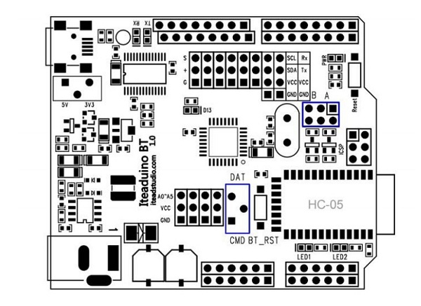
Digital/Servo Interface: D0~D13 pin
Sensor Interface: A0 A1 A2 A3 A4 A5 pin
HC-05 operate mode set switch
There is a 1P2T switch for HC-05 operation mode set. When the switch is set on “DAT” side, the HC-05 will work in the data mode. When the switch is set on “CMD” side, the HC-05 will work in command mode, in this mode, Iteaduino/FT232R could send the AT command to centigrade the HC-05 module (Using Baud Rate 38400).
Communicate mode set jumper
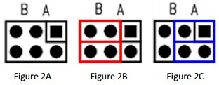
There is a jumper to set the connections of HC-05. When the jumper is set in A, the HC-05 communicates to FT232R, when the jumper is set to B, the HC-05 communicates to Atmega328P(board).
Figure 2A:Communicate mode set jumper
Figure 2B:The jumper is set to B
Figure 2C:The jumper is set to A
Note: Don’t connect the jumpers when in upload sketch, connect them after finish uploading.
Download
Demo Code for Iteaduino BT Master Mode
Fritzing Parts for Iteaduino BT
Useful Link
<Correct Iteaduino BT Datasheet>
By Michael Doherty <Iteaduino BT Test Vedio>
By Benjamin Bellamy <How-To configure and use an Iteaduino BT>
 Notice

