Difference between revisions of "Arduino GPS shield"
From ITEAD Wiki
(→Electrical Characteristics) |
(→Hardware) |
||
| Line 49: | Line 49: | ||
==Hardware== | ==Hardware== | ||
| + | http://imall.iteadstudio.com/media/wysiwyg/Products/IM120417017_Arduino_GPS_shield/IM120417017_ArduinoGPSshield.jpg | ||
| + | |||
| + | Figure 1 Top Map | ||
| + | |||
| + | {| class="wikitable" | ||
| + | |- | ||
| + | | align="center" style="background:#f0f0f0;"|'''Arduino PIN''' | ||
| + | | align="center" style="background:#f0f0f0;"|'''Description''' | ||
| + | |- | ||
| + | | D0||Data | ||
| + | |- | ||
| + | | D1||Din | ||
| + | |- | ||
| + | | D2||- | ||
| + | |- | ||
| + | | D3||- | ||
| + | |- | ||
| + | | D4||- | ||
| + | |- | ||
| + | | D5||- | ||
| + | |- | ||
| + | | D6||- | ||
| + | |- | ||
| + | | D7||- | ||
| + | |- | ||
| + | | D8||- | ||
| + | |- | ||
| + | | D9||- | ||
| + | |- | ||
| + | | D10||CSN | ||
| + | |- | ||
| + | | D11||MOSI | ||
| + | |- | ||
| + | | D12||MISO | ||
| + | |- | ||
| + | | D13||SCK | ||
| + | |- | ||
| + | | A0||Breakout | ||
| + | |- | ||
| + | | A1||Breakout | ||
| + | |- | ||
| + | | A2||Breakout | ||
| + | |- | ||
| + | | A3||Breakout | ||
| + | |- | ||
| + | | A4||IIC_SDA | ||
| + | |- | ||
| + | | A5||IIC_SCL | ||
| + | |} | ||
==Installation== | ==Installation== | ||
Revision as of 06:21, 23 May 2014
Contents
Overview
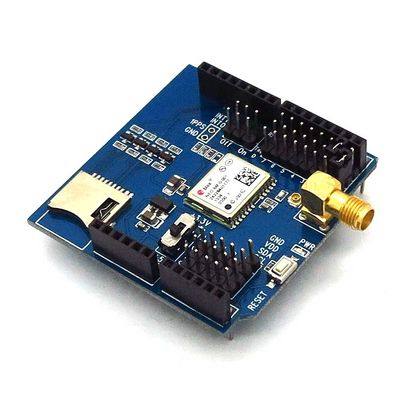
Arduino GPS shield is a GPS module breadout board designed for Global Positioning System receiver with SD interface. It is easy to use for recording the position data into SD card. 5V/3.3V compatible operation voltage level make it compatible with Arduino boards, leaf maple, IFlat32 and other arduino compatible boards.
Features
- With Micro SD interface
- Active antenna design with high receive sensitivity, compatible
normal antenna
- Extremely fast time to first fix at low signal level
- UART interface
- Operation temperature: -40℃ ~ +85℃
Specifications
| PCB size | 55.88mm X 54.1mm X 1.6mm |
| Indicators | PWR |
| Power supply | compatible with Arduino |
| Communication Protocol | UART |
| RoSH | Yes |
Electrical Characteristics
| Parameter | Min. | Typical | Max. | Unit |
| Power voltage | 4.5 | 5 | 5.5 | VDC |
| Input voltage VH | 3 | 5.5 | V | |
| Input voltage VL | -0.3 | 0 | 0.5 | V |
| Baud rate | 38400 | bps |
Hardware

Figure 1 Top Map
| Arduino PIN | Description |
| D0 | Data |
| D1 | Din |
| D2 | - |
| D3 | - |
| D4 | - |
| D5 | - |
| D6 | - |
| D7 | - |
| D8 | - |
| D9 | - |
| D10 | CSN |
| D11 | MOSI |
| D12 | MISO |
| D13 | SCK |
| A0 | Breakout |
| A1 | Breakout |
| A2 | Breakout |
| A3 | Breakout |
| A4 | IIC_SDA |
| A5 | IIC_SCL |
 Notice