Difference between revisions of "Arduino Dual Step Motor Driver Shield"
From ITEAD Wiki
(→Hardware) |
(→Hardware) |
||
| Line 52: | Line 52: | ||
Figure 1 Top Map | Figure 1 Top Map | ||
| − | Arduino Socket | + | Arduino Socket definition: |
| − | + | ||
| − | + | ||
| − | + | ||
{| class="wikitable" | {| class="wikitable" | ||
|- | |- | ||
| + | | align="center" style="background:#f0f0f0;"|'''Pin''' | ||
| + | | align="center" style="background:#f0f0f0;"|'''Description''' | ||
|- | |- | ||
| D0||UART_Rx | | D0||UART_Rx | ||
Revision as of 05:47, 23 May 2014
Contents
Overview
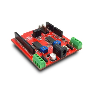
Dual stepper motor driver shield can drive 2 stepper motors at the same time by Arduino. It can work with the power supply from 4.75V to 30V. High accuracy controlling can be supported by Arduino for CNC milling machine.
Features
- Dual step motor driver design for Cartesian coordinate system
- ±750mA, 5-30V output rating
- Automatic current-decay mode detection/selection
- 3.0 to 5.5V logic supply voltage range
- Mixed, fast and slow current-decay modes
- Internal UVLO and thermal shutdown circuitry
- Crossover-current protection
Specifications
| PCB size | 68.33mm X 60.7mm X 1.6mm |
| Indicators | PWR |
| Communication Protocol | UART, IIC |
| RoSH | Yes |
Electrical Characteristics
| Parameter | Min. | Typical | Max. | Unit |
| Power voltage (Vsupply) | 4.75 | - | 30 | VDC |
| Power voltage (Vlogic) | 3 | - | 5.5 | VDC |
| Input voltage VH | 0.7Vlogic | - | - | V |
| Input voltage VL | - | - | 0.3Vlogic | V |
| Current Consumption | - | - | 70 | mA |
Hardware

Figure 1 Top Map
Arduino Socket definition:
| Pin | Description |
| D0 | UART_Rx |
| D1 | UART_Tx |
| D2 | X Step |
| D3 | X Direction |
| D4 | X MS1 setting |
| D5 | X MS2 setting |
| D6 | Y Step |
| D7 | Y Direction |
| D8 | Y MS1 setting |
| D9 | Y MS2 setting |
| D10 | - |
| D11 | - |
| D12 | - |
| D13 | - |
| A0 | ENY |
| A1 | SLEEPY |
| A2 | ENX |
| A3 | SLEEPX |
| A4 | IIC_SCL |
| A5 | IIC_SDA |
 Notice