|
|
| (14 intermediate revisions by 2 users not shown) |
| Line 1: |
Line 1: |
| − | ==Overview==
| + | {| class="FCK__ShowTableBorders" align="left" |
| − | | + | |
| − | [[File:ITDB02-2.4E.jpg|thumb|400px|right]]
| + | |
| − | ITDB02-2.4E module is 2.4" TFT LCD with 65K color 320 x 240 resolutions. The controller of this LCD module is S6D1121, it supports 8bit / 16bit data interface with 4 wires control interface. Moreover, this module includes the touch screen and SD card socket.
| + | |
| − | | + | |
| − | ==Features==
| + | |
| − | * Compatible with 3.3/5V operation voltage level
| + | |
| − | * 8bits/16bits operation compatible
| + | |
| − | * Compatible with UTFT library
| + | |
| − | * With SD Card Socket
| + | |
| − | | + | |
| − | ==Specifications==
| + | |
| − | {| border="1" | + | |
| − | | + | |
| − | | PCB size||65.53mm X 50.8mm X 1.6mm
| + | |
| | |- | | |- |
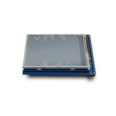
| − | | Power supply||5V DC | + | | [[File:ITDB02-2.4E-display-4.jpg|400px|ITDB02-2.4E V2]] <br> |
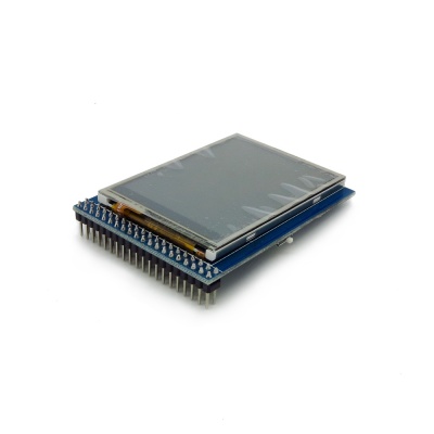
| | + | | [[File:ITDB02-2.4E-display-3.jpg|400px|ITDB02-2.4E V1]]<br> |
| | |- | | |- |
| − | | RoHS||Yes | + | | <div style="text-align: center">[[ITDB02-2.4E V2|ITDB02-2.4E V2(SKU:IM160418002)]]</div> |
| | + | | <div style="text-align: center">[[ITDB02-2.4E V1|ITDB02-2.4E V1(SKU:IM120419004))]]</div> |
| | |} | | |} |
| | + | <br clear="all"> |
| | | | |
| − | ==Electrical Characteristics== | + | ==V2 Change List== |
| − | {| class="wikitable"
| + | * V2 and V1 almost the same, but they use different driver IC. |
| − | |-
| + | |
| − | | align="center" style="background:#f0f0f0;"|'''Parameter'''
| + | |
| − | | align="center" style="background:#f0f0f0;"|'''Min.'''
| + | |
| − | | align="center" style="background:#f0f0f0;"|'''Typical'''
| + | |
| − | | align="center" style="background:#f0f0f0;"|'''Max.'''
| + | |
| − | | align="center" style="background:#f0f0f0;"|'''Unit'''
| + | |
| − | |-
| + | |
| − | | Power voltage||4.5||5||5.5||VDC
| + | |
| − | |-
| + | |
| − | | Input voltage VinH (Target Voltage = 3.3V)||3||3.3||3.6||V
| + | |
| − | |-
| + | |
| − | | Input voltage VinH (Target Voltage = 5V)||4.5||5||5.5||V
| + | |
| − | |-
| + | |
| − | | Input voltage VinL||-0.3||0||0.5||V
| + | |
| − | |-
| + | |
| − | | Current Consumption||-||20||40||mA
| + | |
| − | |}
| + | |
| − | | + | |
| − | ==Hardware==
| + | |
| − | http://imall.iteadstudio.com/media/wysiwyg/Products/TFTLCDs/IM120419004_ITDB02_2.4E.jpg
| + | |
| − | | + | |
| − | Bottom View
| + | |
| − | | + | |
| − | Pin Map list
| + | |
| − | | + | |
| − | {| class="wikitable"
| + | |
| − | |-
| + | |
| − | | align="center" style="background:#f0f0f0;"|'''Pin'''
| + | |
| − | | align="center" style="background:#f0f0f0;"|'''Type*'''
| + | |
| − | | align="center" style="background:#f0f0f0;"|'''Description'''
| + | |
| − | |-
| + | |
| − | | GND||G||Ground
| + | |
| − | |-
| + | |
| − | | VCC||P||5V Power Supply pin
| + | |
| − | |-
| + | |
| − | | NC||-||No connection
| + | |
| − | |-
| + | |
| − | | RS||I||Data/Command selection
| + | |
| − | |-
| + | |
| − | | WR||I||Write signal enable, low active
| + | |
| − | |-
| + | |
| − | | RD||I||Read signal enable, low active
| + | |
| − | |-
| + | |
| − | | DB8||I||Data Bus
| + | |
| − | |-
| + | |
| − | | DB9||I||Data Bus
| + | |
| − | |-
| + | |
| − | | DB10||I||Data Bus
| + | |
| − | |-
| + | |
| − | | DB11||I||Data Bus
| + | |
| − | |-
| + | |
| − | | DB12||I||Data Bus
| + | |
| − | |-
| + | |
| − | | DB13||I||Data Bus
| + | |
| − | |-
| + | |
| − | | DB14||I||Data Bus
| + | |
| − | |-
| + | |
| − | | DB15||I||Data Bus
| + | |
| − | |-
| + | |
| − | | CS||I||Chip Selection,Low level active
| + | |
| − | |-
| + | |
| − | | NC||-||No connection
| + | |
| − | |-
| + | |
| − | | LED||P||Backlight
| + | |
| − | |-
| + | |
| − | | NC||-||No connection
| + | |
| − | |-
| + | |
| − | | DB0||-||No connection(8bit mode)
| + | |
| − | |-
| + | |
| − | | DB0||I||Data Bus(16bit mode)
| + | |
| − | |-
| + | |
| − | | DB1||-||No connection(8bit mode)
| + | |
| − | |-
| + | |
| − | | DB1||I||Data Bus(16bit mode)
| + | |
| − | |-
| + | |
| − | | DB2||-||No connection(8bit mode)
| + | |
| − | |-
| + | |
| − | | DB2||I||Data Bus(16bit mode)
| + | |
| − | |-
| + | |
| − | | DB3||-||No connection(8bit mode)
| + | |
| − | |-
| + | |
| − | | DB3||I||Data Bus(16bit mode)
| + | |
| − | |-
| + | |
| − | | DB4||-||No connection(8bit mode)
| + | |
| − | |-
| + | |
| − | | DB4||I||Data Bus(16bit mode)
| + | |
| − | |-
| + | |
| − | | DB5||-||No connection(8bit mode)
| + | |
| − | |-
| + | |
| − | | DB5||I||Data Bus(16bit mode)
| + | |
| − | |-
| + | |
| − | | DB6||-||No connection(8bit mode)
| + | |
| − | |-
| + | |
| − | | DB6||I||Data Bus(16bit mode)
| + | |
| − | |-
| + | |
| − | | DB7||-||No connection(8bit mode)
| + | |
| − | |-
| + | |
| − | | DB7||I||Data Bus(16bit mode)
| + | |
| − | |-
| + | |
| − | | T_CLK||I||Touch clock
| + | |
| − | |-
| + | |
| − | | T_CS||I||Touch chip selection
| + | |
| − | |-
| + | |
| − | | T_DIN||I||Touch data input
| + | |
| − | |-
| + | |
| − | | T_BUSY||O||Touch status
| + | |
| − | |-
| + | |
| − | | T_DOUT||O||Touch data output
| + | |
| − | |-
| + | |
| − | | T_IRQ||O||Touch interrupt
| + | |
| − | |-
| + | |
| − | | SD_SO||O||SD MISO
| + | |
| − | |-
| + | |
| − | | SD_SCK||I||SD SCK
| + | |
| − | |-
| + | |
| − | | SD_SI||I||SD MOSI
| + | |
| − | |-
| + | |
| − | | SD_NSS||I||SD NSS
| + | |
| − | |-
| + | |
| − | | NC||-||No connection
| + | |
| − | |-
| + | |
| − | | NC||-||No connection
| + | |
| − | |}
| + | |
| − | | + | |
| − | Type *:P: Power supply; G:Ground; I:Input; O:Output;
| + | |
| − | | + | |
| − | The ITDB02_2.4E uses the S6D1121 controller , it support 8/16bit data interface. The touch IC is TSC2046.
| + | |
| − | | + | |
| − | ==Installation==
| + | |
| − | | + | |
| − | ==Download==
| + | |
| − | | + | |
| − | ==Useful Links==
| + | |


 Notice