Difference between revisions of "Iteaduino ADK"
m (→Pin Mapping) |
m (→Features) |
||
| Line 20: | Line 20: | ||
* Arduino Mega 2560 compatible (256K Flash MCU) | * Arduino Mega 2560 compatible (256K Flash MCU) | ||
* Simply works like an Arduino Mega with an integrated USB [[Shield]] | * Simply works like an Arduino Mega with an integrated USB [[Shield]] | ||
| − | * 56 Digital IOs,16 Analog | + | * 56 Digital IOs,16 Analog inputs,14 PWM outputs |
* 4 Hardware serial ports (UART),1 Hardware TWI (I2C),1 Hardware SPI (up to 8Mbps) | * 4 Hardware serial ports (UART),1 Hardware TWI (I2C),1 Hardware SPI (up to 8Mbps) | ||
* On board USB host(MAX3421) | * On board USB host(MAX3421) | ||
Latest revision as of 02:24, 24 November 2015
Overview
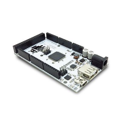
Iteaduino ADK Main Board is based on Android Open Accessory Development Kit(ADK). Using this ADK Main Board you can build your own mobile accessories. Open Source Android development platform and Iteaduino ADK Main Board is an ideal solution for mobile based Home Automation.
Iteaduino ADK will make Android devices interact with the physical world. As an Arduino compatible platform with 256K Flash. On board USB host makes it easy to interact with USB devices like pen drivers, keyboard, mouse, Bluetooth dongles.
What is Android Open Accessory Development Kit?
The Android 3.1 platform (also backported to Android 2.3.4) introduces Android Open Accessory support, which allows external USB hardware (an Android USB accessory) to interact with an Android-powered device in a special "accessory" mode. When an Android-powered powered device is in accessory mode, the connected accessory acts as the USB host (powers the bus and enumerates devices) and the Android-powered device acts as the device.
Android USB accessories are specifically designed to attach to Android-powered devices and adhere to a simple protocol (Android accessory protocol) that allows them to detect Android-powered devices that support accessory mode. Accessories must also provide 500mA at 5V for charging power. Many previously released Android-powered devices are only capable of acting as a USB device and cannot initiate connections with external USB devices. Android Open Accessory support overcomes this limitation and allows you to build accessories that can interact with an assortment of Android-powered devices by allowing the accessory to initiate the connection.
Go shopping Iteaduino ADK (SKU:IM120411005)
Features
- Android Open Accessories development Kit (ADK) compatible
- Supports Android v2.3.4 and above devices
- Works with Android Debug Bridge (ADB) using MicroBridge
- Supports Android v1.5 and above devices
- Arduino Mega 2560 compatible (256K Flash MCU)
- Simply works like an Arduino Mega with an integrated USB Shield
- 56 Digital IOs,16 Analog inputs,14 PWM outputs
- 4 Hardware serial ports (UART),1 Hardware TWI (I2C),1 Hardware SPI (up to 8Mbps)
- On board USB host(MAX3421)
- On board USB slave(ATMega8U2) and ISP breakout
- Build-in 5V-2A switched power regulator (input range 7V - 23V)
Spec
| Microcontroller | ATMega2560 |
| Max Frequency | 16MHz |
| RAM Capacity | 8K |
| FLASH Capacity | 256K |
| Power Supply | External 12V/External 24V/External 7V/External 9V/USB 5V |
| I/O Operation Level | 5V |
| Board Size | 102mm x 54mm |
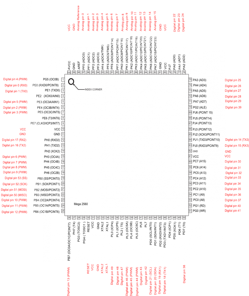
Pin Mapping
| Pin Number | Pin Name | Mapped Pin Name |
| 1 | PG5 ( OC0B ) | Digital pin 4 (PWM) |
| 2 | PE0 ( RXD0/PCINT8 ) | Digital pin 0 (RX0) |
| 3 | PE1 ( TXD0 ) | Digital pin 1 (TX0) |
| 4 | PE2 ( XCK0/AIN0 ) | |
| 5 | PE3 ( OC3A/AIN1 ) | Digital pin 5 (PWM) |
| 6 | PE4 ( OC3B/INT4 ) | Digital pin 2 (PWM) |
| 7 | PE5 ( OC3C/INT5 ) | Digital pin 3 (PWM) |
| 8 | PE6 ( T3/INT6 ) | |
| 9 | PE7 ( CLKO/ICP3/INT7 ) | |
| 10 | VCC | VCC |
| 11 | GND | GND |
| 12 | PH0 ( RXD2 ) | Digital pin 17 (RX2) |
| 13 | PH1 ( TXD2 ) | Digital pin 16 (TX2) |
| 14 | PH2 ( XCK2 ) | |
| 15 | PH3 ( OC4A ) | Digital pin 6 (PWM) |
| 16 | PH4 ( OC4B ) | Digital pin 7 (PWM) |
| 17 | PH5 ( OC4C ) | Digital pin 8 (PWM) |
| 18 | PH6 ( OC2B ) | Digital pin 9 (PWM) |
| 19 | PB0 ( SS/PCINT0 ) | Digital pin 53 (SS) |
| 20 | PB1 ( SCK/PCINT1 ) | Digital pin 52 (SCK) |
| 21 | PB2 ( MOSI/PCINT2 ) | Digital pin 51 (MOSI) |
| 22 | PB3 ( MISO/PCINT3 ) | Digital pin 50 (MISO) |
| 23 | PB4 ( OC2A/PCINT4 ) | Digital pin 10 (PWM) |
| 24 | PB5 ( OC1A/PCINT5 ) | Digital pin 11 (PWM) |
| 25 | PB6 ( OC1B/PCINT6 ) | Digital pin 12 (PWM) |
| 26 | PB7 ( OC0A/OC1C/PCINT7 ) | Digital pin 13 (PWM) |
| 27 | PH7 ( T4 ) | |
| 28 | PG3 ( TOSC2 ) | |
| 29 | PG4 ( TOSC1 ) | |
| 30 | RESET | RESET |
| 31 | VCC | VCC |
| 32 | GND | GND |
| 33 | XTAL2 | XTAL2 |
| 34 | XTAL1 | XTAL1 |
| 35 | PL0 ( ICP4 ) | Digital pin 49 |
| 36 | PL1 ( ICP5 ) | Digital pin 48 |
| 37 | PL2 ( T5 ) | Digital pin 47 |
| 38 | PL3 ( OC5A ) | Digital pin 46 (PWM) |
| 39 | PL4 ( OC5B ) | Digital pin 45 (PWM) |
| 40 | PL5 ( OC5C ) | Digital pin 44 (PWM) |
| 41 | PL6 | Digital pin 43 |
| 42 | PL7 | Digital pin 42 |
| 43 | PD0 ( SCL/INT0 ) | Digital pin 21 (SCL) |
| 44 | PD1 ( SDA/INT1 ) | Digital pin 20 (SDA) |
| 45 | PD2 ( RXDI/INT2 ) | Digital pin 19 (RX1) |
| 46 | PD3 ( TXD1/INT3 ) | Digital pin 18 (TX1) |
| 47 | PD4 ( ICP1 ) | |
| 48 | PD5 ( XCK1 ) | |
| 49 | PD6 ( T1 ) | |
| 50 | PD7 ( T0 ) | Digital pin 38 |
| 51 | PG0 ( WR ) | Digital pin 41 |
| 52 | PG1 ( RD ) | Digital pin 40 |
| 53 | PC0 ( A8 ) | Digital pin 37 |
| 54 | PC1 ( A9 ) | Digital pin 36 |
| 55 | PC2 ( A10 ) | Digital pin 35 |
| 56 | PC3 ( A11 ) | Digital pin 34 |
| 57 | PC4 ( A12 ) | Digital pin 33 |
| 58 | PC5 ( A13 ) | Digital pin 32 |
| 59 | PC6 ( A14 ) | Digital pin 31 |
| 60 | PC7 ( A15 ) | Digital pin 30 |
| 61 | VCC | VCC |
| 62 | GND | GND |
| 63 | PJ0 ( RXD3/PCINT9 ) | Digital pin 15 (RX3) |
| 64 | PJ1 ( TXD3/PCINT10 ) | Digital pin 14 (TX3) |
| 65 | PJ2 ( XCK3/PCINT11 ) | |
| 66 | PJ3 ( PCINT12 ) | |
| 67 | PJ4 ( PCINT13 ) | |
| 68 | PJ5 ( PCINT14 ) | |
| 69 | PJ6 ( PCINT 15 ) | |
| 70 | PG2 ( ALE ) | Digital pin 39 |
| 71 | PA7 ( AD7 ) | Digital pin 29 |
| 72 | PA6 ( AD6 ) | Digital pin 28 |
| 73 | PA5 ( AD5 ) | Digital pin 27 |
| 74 | PA4 ( AD4 ) | Digital pin 26 |
| 75 | PA3 ( AD3 ) | Digital pin 25 |
| 76 | PA2 ( AD2 ) | Digital pin 24 |
| 77 | PA1 ( AD1 ) | Digital pin 23 |
| 78 | PA0 ( AD0 ) | Digital pin 22 |
| 79 | PJ7 | |
| 80 | VCC | VCC |
| 81 | GND | GND |
| 82 | PK7 ( ADC15/PCINT23 ) | Analog pin 15 |
| 83 | PK6 ( ADC14/PCINT22 ) | Analog pin 14 |
| 84 | PK5 ( ADC13/PCINT21 ) | Analog pin 13 |
| 85 | PK4 ( ADC12/PCINT20 ) | Analog pin 12 |
| 86 | PK3 ( ADC11/PCINT19 ) | Analog pin 11 |
| 87 | PK2 ( ADC10/PCINT18 ) | Analog pin 10 |
| 88 | PK1 ( ADC9/PCINT17 ) | Analog pin 9 |
| 89 | PK0 ( ADC8/PCINT16 ) | Analog pin 8 |
| 90 | PF7 ( ADC7 ) | Analog pin 7 |
| 91 | PF6 ( ADC6 ) | Analog pin 6 |
| 92 | PF5 ( ADC5/TMS ) | Analog pin 5 |
| 93 | PF4 ( ADC4/TMK ) | Analog pin 4 |
| 94 | PF3 ( ADC3 ) | Analog pin 3 |
| 95 | PF2 ( ADC2 ) | Analog pin 2 |
| 96 | PF1 ( ADC1 ) | Analog pin 1 |
| 97 | PF0 ( ADC0 ) | Analog pin 0 |
| 98 | AREF | Analog Reference |
| 99 | GND | GND |
| 100 | AVCC | VCC |
 Notice
