Difference between revisions of "Iteaduino Leonardo"
(→Electrical Characteristics) |
(→Pin Map) |
||
| Line 67: | Line 67: | ||
==Pin Map== | ==Pin Map== | ||
| + | {| class="wikitable" | ||
| + | |- | ||
| + | | align="center" style="background:#f0f0f0;"|'''Index''' | ||
| + | | align="center" style="background:#f0f0f0;"|'''Name of Arduino''' | ||
| + | | align="center" style="background:#f0f0f0;"|'''Alternate Function''' | ||
| + | | align="center" style="background:#f0f0f0;"|'''Pin of Atmega32u4''' | ||
| + | |- | ||
| + | | 1||D0||UART DIN||PD2 | ||
| + | |- | ||
| + | | 2||D1||UART DOUT||PD3 | ||
| + | |- | ||
| + | | 3||D2||IIC_SDA||PD1 | ||
| + | |- | ||
| + | | 4||D3||IIC_SCL/PWM||PD0 | ||
| + | |- | ||
| + | | 5||D4||External Interrupt 0/A6||PD4 | ||
| + | |- | ||
| + | | 6||D5||External Interrupt 1/PWM||PC5 | ||
| + | |- | ||
| + | | 7||D6||PWM||PD7 | ||
| + | |- | ||
| + | | 8||D7||A7||PE6 | ||
| + | |- | ||
| + | | 9||D8||A8||PB4 | ||
| + | |- | ||
| + | | 10||D9||PWM/A9||PB5 | ||
| + | |- | ||
| + | | 11||D10||PWM/A10||PB6 | ||
| + | |- | ||
| + | | 12||D11||PWM||PB7 | ||
| + | |- | ||
| + | | 13||D12||A11||PD6 | ||
| + | |- | ||
| + | | 14||D13||PWM||PC7 | ||
| + | |- | ||
| + | | 15||A0||||PF7 | ||
| + | |- | ||
| + | | 16||A1||||PF6 | ||
| + | |- | ||
| + | | 17||A2||||PF5 | ||
| + | |- | ||
| + | | 18||A3||||PF4 | ||
| + | |- | ||
| + | | 19||A4||||PF1 | ||
| + | |- | ||
| + | | 20||A5||||PF0 | ||
| + | |} | ||
==Power Supply== | ==Power Supply== | ||
Revision as of 07:30, 20 May 2014
Contents
Overview
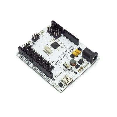
Iteaduino Leonardo is a microcontroller board based on the ATmega32u4, it's 100% campatible with Arduino Leonardo. It has 20 digital input/output pins, a 16 MHz crystal oscillator, a micro USB connection, a power jack, an ICSP header, and a reset button. It contains everything needed to support the microcontroller; simply connect it to a computer with a USB cable or power it with an AC-to-DC adapter or battery to get started.
Iteaduino Leonardo differs from all preceding boards in that the ATmega32u4 has built-in USB communication, eliminating the need for a secondary processor. This allows the Leonardo to appear to a connected computer as a mouse and keyboard, in addition to a virtual (CDC) serial / COM port. It also has other implications for the behavior of the board.
Features
- Efficient DC-DC Power supply with wide range input.
- 3.3V/5V Operating Voltage selection
- All pins out for Sensor and Servo
- UART/IIC interface breakout
- All electronic brick socket are broken out
Spec
| Microprocessor | ATmega32U4 |
| PCB Size | 68.58mm X 58.42mm X 1.6mm |
| Indicators | Power,TX,RX,L |
| Power supply(recommended) | 7-23V DC |
| Power supply(limits) | 23 VDC(max) |
| Communication Protocol | UART,SPI,IIC |
| Clock Speed | 16MHz |
| RoHS | Yes |
Electrical Characteristics
| Specification | Min | Type | Max | Unit |
| Input voltage | 7 | - | 23 | VDC |
| Operating Voltage | - | 3.3/5 | - | VDC |
| DC Current per I/O Pin | - | 40 | - | mA |
Hardware
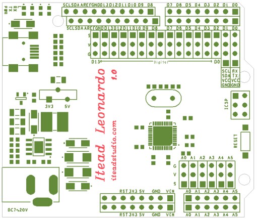
Digital/Servo Interface: D0~D13 pin
Sensor Interface: A0 A1 A2 A3 A4 A5 pin
Pin Map
| Index | Name of Arduino | Alternate Function | Pin of Atmega32u4 |
| 1 | D0 | UART DIN | PD2 |
| 2 | D1 | UART DOUT | PD3 |
| 3 | D2 | IIC_SDA | PD1 |
| 4 | D3 | IIC_SCL/PWM | PD0 |
| 5 | D4 | External Interrupt 0/A6 | PD4 |
| 6 | D5 | External Interrupt 1/PWM | PC5 |
| 7 | D6 | PWM | PD7 |
| 8 | D7 | A7 | PE6 |
| 9 | D8 | A8 | PB4 |
| 10 | D9 | PWM/A9 | PB5 |
| 11 | D10 | PWM/A10 | PB6 |
| 12 | D11 | PWM | PB7 |
| 13 | D12 | A11 | PD6 |
| 14 | D13 | PWM | PC7 |
| 15 | A0 | PF7 | |
| 16 | A1 | PF6 | |
| 17 | A2 | PF5 | |
| 18 | A3 | PF4 | |
| 19 | A4 | PF1 | |
| 20 | A5 | PF0 |
Power Supply
Memory
Input and Output
Communication
Programming
Automatic (Software) Reset and Bootloader
Initiation
USB Over-current Protection
Physical Characteristics
Download
Datasheet for Iteaduino Leonardo
Schematic for Iteaduino Leonardo
Fritzing Parts for Iteaduino Leonardo
 Notice
