Difference between revisions of "Wee Serial WIFI Module"
m (→Hardware) |
m (→Hardware) |
||
| Line 43: | Line 43: | ||
[[File:IM141118001pic2.jpg|500px]] | [[File:IM141118001pic2.jpg|500px]] | ||
[[File:IM141118001pic4.jpg|500px]] | [[File:IM141118001pic4.jpg|500px]] | ||
| + | |||
| + | '''Note''' | ||
| + | |||
| + | *Work/FW Switch | ||
| + | :When burn firmware into ESP8266, you should ensure the switch is in FW mode. | ||
| + | :For the normal usage of this module, you should ensure the switch is in work mode. | ||
==Pin Map== | ==Pin Map== | ||
Revision as of 07:04, 10 December 2014
Contents
Overview
Wee is a WIFI module based on ESP8266 SoC. ESP8266 comes out of nowhere and has been taking by storm the IoT world. You can find many hacking projects about it on the internet. So far, the most popular ESP8266 breakout version only has GPIO0 and GPIO2 routed to the header. Compared to it, Wee WIFI module is designed with a standard Bee interface and has more GPIOs available for developers. In a word, users can take full use of the utility of ESP8266 SoC by using Wee WIFI module in your projects.
Go shopping [Wee Serial WIFI Module]
Features
- Standard Bee interface
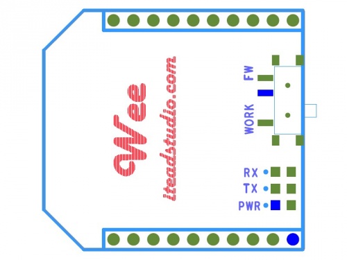
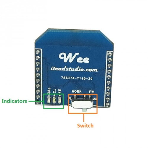
- indicators: TX, RX, PWR
- FW/Work Switch – when burn firmware into ESP8266, you should ensure the switch is in FW status. For the normal usage of this module, you should ensure the switch is in work status.
- More GPIOs help developer take full use of the utility of ESP8266 SoC
Specification
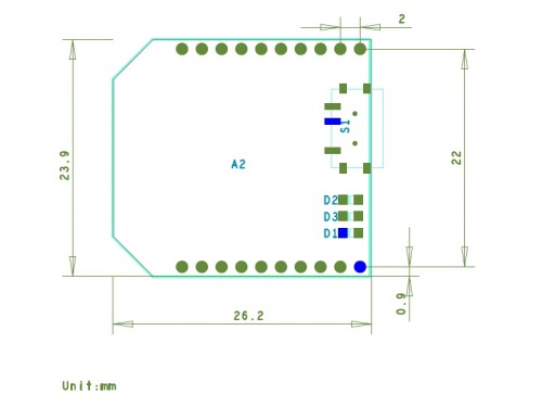
| PCB Size | 23.9X26.2X1.6mm |
| Interface | Bee interface |
| Indicators | PWR,TX,RX |
Electrical Characteristics
| Characteristics | Symbol | Min | Typ | Max | Unit |
| Power supply voltage | VDD | 3 | 3.3 | 3.5 | V |
| High input voltage | VIH | 0.8XVDD | - | VDD | V |
| Low input voltage | VIL | 0 | - | 0.2XVDD | V |
| Operation current for VDD | IDD | - | - | 215 | mA |
Hardware
Note
- Work/FW Switch
- When burn firmware into ESP8266, you should ensure the switch is in FW mode.
- For the normal usage of this module, you should ensure the switch is in work mode.
Pin Map
| Pin Index | Pin Name | Description |
| 1 | 3V3 | |
| 2 | TX | |
| 3 | RX | |
| 4 | - | |
| 5 | RST# | Enable wee module to reset in low level |
| 6 | - | |
| 7 | FW | Firmware enable pin* |
| 8 | - | |
| 9 | - | |
| 10 | GND | |
| 11 | - | |
| 12 | - | |
| 13 | - | |
| 14 | - | |
| 15 | - | |
| 16 | - | |
| 17 | IO4 | |
| 18 | IO3 | |
| 19 | IO2 | |
| 20 | IO1 |
Note: Firmware enable pin
- When set to 0, reset the wee module and enable the firmware uploading mode;
- When set to 1, reset the wee module and enable the normal work mode
Instruction
AT Commands
 Notice

