Difference between revisions of "Gboard"
m (→Overview) |
m (→Hardware) |
||
| Line 51: | Line 51: | ||
[[File:GBoard1.jpg]] | [[File:GBoard1.jpg]] | ||
| − | Top View Map | + | Top View Map |
| − | + | ||
| − | + | ||
==UART Setting Jumpers== | ==UART Setting Jumpers== | ||
Revision as of 02:42, 24 November 2014
Contents
Overview
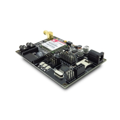
Gboard is a unique Arduino board which features a SIM900 GSM/GPRS module, an XBee socket, nRF24L01+ module interface and an ATMega328P controller. This board will add wireless XBee / nRF24L01+ control as well as GSM/GPRS connectivity to your projects. It’s great for anything from home automation to robot control. The possibilities are endless!
Gboard can be used as a GSM/GPRS data transfer or wireless communication project development platform. Gboard support wide range power supply and Micro SD for mass storage. There are some 3pin electronic brick/ sensor brick interface breakout on board, it offer an easy way for a quick prototyping. The board requires FTDI basic board to upload sketch, you can use our Foca board to do it.
Note:
- 1. There is no USB connector on the board nor is there any USB hardware, you have to use a serial connection or ICSP.
- 2. When you upload sketch to Gboard, please choose the board Arduino Duemilanove w/ ATmega328Bootloader.
- 3. The bootloarder file is ATmegaBOOT_168_atmega328.hex, you can find it in the directory arduino\hardware\arduino\bootloaders\atmega
- 4. The serial interface (bootloader connection) is 3.3v, not the typical 5v as on many Arduino boards - anyone using an alternative to the Foca board must take note not to risk damage.
Go shopping Gboard (SKU:IM120411004)
Spec
| PCB size | 88.1mm X 60.7mm X 1.6mm |
| Power supply | 7-23V DC |
| Microprocessor | Atmega328 |
| Indicators | PWR, Status, NET |
| RoHS | Yes |
Electrical Characteristics
| Specification | Min. | Typical Value | Max. | Unit |
|---|---|---|---|---|
| Power Voltage | 7 | - | 23 | VDC |
| Input Voltage VH (Target Voltage = 3.3V) | 3 | 3.3 | 3.6 | V |
| Input Voltage VL: | -0.3 | 0 | 0.5 | V |
| Current Consumption | - | 100 | 500 | mA |
Hardware
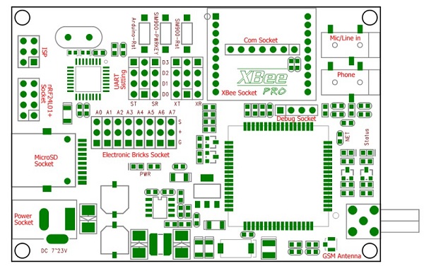
Top View Map
UART Setting Jumpers
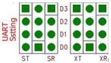
The SIM900 module and XBee module communicate to ATMega328 through UART. They cannot be used with the same port at the same time, so there are two UART setting jumpers to configure the UART communication. The figure of UART setting jumpers is as below.
Figure of UART setting jumpers
D0 and D1 are hardware UART ports of Arduino. D2 and D3 are digital GPIO of Arduino. There are two configurations to set the UART communication.
ST: UART Tx of SIM900 module
SR: UART Rx of SIM900 module
XT: XBee Tx of XBee module
XR: XBee Rx of XBee module
Power and reset connection of SIM900
In the GBoard, the PWRKEY and RESET pins of SIM900 module connect to Arduino as list below.
| Arduino pin | SIM900 pin | Enable |
|---|---|---|
| D6 | PWR | High level Active |
| D7 | RESET | High level Active |
Software
Gboard is designed for compatible for SD Library of Arduino.
With embedded bootloader, Gboard is easy to use by Arduino IDE through Foca series. ISP of Atmega328 is broke out for download firmware easily.
Download
Useful Link
- <Fritzing Parts: ITEAD Development Board>
- StoveRemote Demo by ModernBotanist
- This demo is based on the example of Arduino Labs. The maker uses it in ITEAD Gboard 1.0 to remote trigger a wood pallet stove.
 Notice


