Difference between revisions of "POE W5500 Ethernet Shield"
m (→Overview) |
m (→Useful Link) |
||
| (4 intermediate revisions by the same user not shown) | |||
| Line 5: | Line 5: | ||
WIZnet's Hardwired TCP/IP is the market-proven technology that supports TCP, UDP, IPv4, ICMP, ARP, IGMP, and PPPoE protocols. W5500 embeds the 32Kbyte internal memory buffer for the Ethernet packet processing. If you use W5500, you can implement the Ethernet application just by adding the simple socket program. It's faster and easier way rather than using any other Embedded Ethernet solution. Users can use 8 independent hardware sockets simultaneously. | WIZnet's Hardwired TCP/IP is the market-proven technology that supports TCP, UDP, IPv4, ICMP, ARP, IGMP, and PPPoE protocols. W5500 embeds the 32Kbyte internal memory buffer for the Ethernet packet processing. If you use W5500, you can implement the Ethernet application just by adding the simple socket program. It's faster and easier way rather than using any other Embedded Ethernet solution. Users can use 8 independent hardware sockets simultaneously. | ||
| − | Go shopping [POE W5500 Ethernet | + | Go shopping [http://imall.iteadstudio.com/im140725005.html POE W5500 Ethernet Shield(IM140725005)] |
==Features== | ==Features== | ||
*3.3/5V level | *3.3/5V level | ||
*On-board micro SD card slot | *On-board micro SD card slot | ||
| − | *Support Endspan and Midspan Modes POE | + | *Support Endspan and Midspan Modes POE |
*Supports following Hardwired TCP/IP Protocols: TCP, UDP, ICMP, IPv4, ARP, IGMP, PPPoE | *Supports following Hardwired TCP/IP Protocols: TCP, UDP, ICMP, IPv4, ARP, IGMP, PPPoE | ||
*Supports 8 independent sockets simultaneously | *Supports 8 independent sockets simultaneously | ||
| Line 171: | Line 171: | ||
==Useful Link== | ==Useful Link== | ||
| − | *[http://www.bb-elec.com/Learning-Center/All-White-Papers/Ethernet/Power-over-Ethernet-PoE.aspx How does PoE work?] | + | 【From Phillip Stevens】 |
| − | + | ||
| + | Prepared an integrated W5500 / W5200 / W5100 code here. | ||
| + | *One socket.h/.c interface. | ||
| + | *Based on freeRTOS for AVR (Arduino). | ||
| + | |||
| + | *freeRTOS/lib_iinchip | ||
| + | *freeRTOS/lib_inet | ||
| + | |||
| + | *https://sourceforge.net/projects/avrfreertos/ | ||
| + | |||
| + | [http://www.bb-elec.com/Learning-Center/All-White-Papers/Ethernet/Power-over-Ethernet-PoE.aspx How does PoE work?] | ||
| + | |||
| + | [http://blog.industrialnetworking.com/2011/12/power-over-ethernet-poe-mode-aendspan.html What's the difference between Mode A/Endspan and Mode B/Midspan?] | ||
Latest revision as of 02:35, 12 November 2014
Contents
Overview
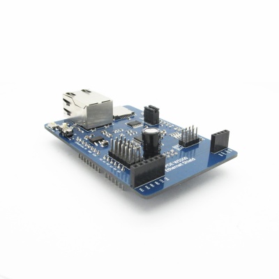
W5500 Ethernet shield is a WIZnet W5500 breakout board with POE and Micro-SD designed for Arduino platform. 5V/3.3V compatible operation voltage level makes it compatible with Arduino boards, leafmaple, and other Arduino compatible board.
WIZnet's Hardwired TCP/IP is the market-proven technology that supports TCP, UDP, IPv4, ICMP, ARP, IGMP, and PPPoE protocols. W5500 embeds the 32Kbyte internal memory buffer for the Ethernet packet processing. If you use W5500, you can implement the Ethernet application just by adding the simple socket program. It's faster and easier way rather than using any other Embedded Ethernet solution. Users can use 8 independent hardware sockets simultaneously.
Go shopping POE W5500 Ethernet Shield(IM140725005)
Features
- 3.3/5V level
- On-board micro SD card slot
- Support Endspan and Midspan Modes POE
- Supports following Hardwired TCP/IP Protocols: TCP, UDP, ICMP, IPv4, ARP, IGMP, PPPoE
- Supports 8 independent sockets simultaneously
- Supports Power down mode
- Supports Wake on LAN over UDP
- Supports High Speed Serial Peripheral Interface (SPI MODE 0, 3)
- Internal 32Kbytes Memory for Tx/Rx Buffers
- 10BaseT/100BaseTX Ethernet PHY embedded
- Support Auto Negotiation (Full and half duplex, 10 and 100-based)
- Not support IP Fragmentation
Specification
| PCB size | 83.82mm X 57.91mm X 1.6mm |
| Power supply | 5V DC |
| Indicator | SPD,LINK,DUP,ACT |
| Communication Protocol | SPI |
Electronic Characteristics
| Parameter | Min. | Typical | Max. | Unit |
| Power supply | 4.5 | 5 | 5.5 | VDC |
| Input voltage VinH(Target voltage=3.3V) | 3 | 3.3 | 3.6 | V |
| Input voltage VinH(Target voltage=5V) | 4.5 | 5 | 5.5 | V |
| Input voltage VinL | -0.3 | 0 | 0.5 | V |
| Current Consumption | - | - | 150 | mA |
Hardware
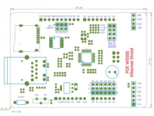
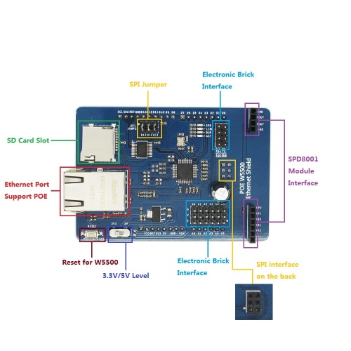
- Indicator LED
- - SPD:Speed LED. This shows the speed status of the connected link.
- ON:100Mbps
- OFF:10Mbps
- - LINK:Link LED. This shows the Link status.
- ON:Link is established
- OFF:Links is not established
- - DUP:Duplex LED. This shows the Duplex status for the connected link.
- ON:Full-duplex mode
- OFF:Half-duplex mode
- - ACT:Active LED. This shows that there is carrier sense(CRS) from the active Physical Medium Sub-layer(PMD) during TX or RX activity.
- ON:Carrier sense from the active PMD
- OFF:No carrier sense
- Reset
- It will reset W5500 if you press this button.
Pin Map
| Pin | Description |
| D0 | Rx/Breakout |
| D1 | TX/Breakout |
| D4 | SD_CS |
| D10 | W5500_CS |
| D11 | SPI MOSI |
| D12 | SPI MISO |
| D13 | SPI SCK |
| A0 | Breakout |
| A1 | Breakout |
| A2 | Breakout |
| A3 | Breakout |
| A4 | IIC_SDA/Breakout |
| A5 | IIC_SCL/Breakout |
| A0 | Breakout |
Installation
When install W5500 Ethernet shield to Iteaduino, please check the operation voltage level of development board. If the voltage is 3.3V (IFLAT32,Leafmaple), set the Operation Level Setting switch to 3.3V. If the voltage is 5V(Arduino), set the Operation Level Setting switch to 5V.
Iteaduino communicates with both the W5500 and SD card using the SPI bus. This is on digital pins 11, 12, and 13 on the UNO/Duemilanove and pins 50, 51, and 52 on the Mega. On both boards, pin 10 is used to select the W5500 and pin 4 for the SD card. These pins cannot be used for general I/O. On the Mega, the hardware SS pin, 53, is not used to select either the W5500 or the SD card, but it must be kept as an output.
Note that because the W5100 and SD card share the SPI bus, only one can be active at a time. If you are using both peripherals in your program, this should be taken care of by the corresponding libraries. If you're not using one of the peripherals in your program, however, you'll need to explicitly deselect it. To do this with the SD card, set pin 4 as an output and write a high to it. For the W5500, set digital pin 10 as a high output.
For some of the Arduino boards, SPI is on ICSP and D11 ~ D13, while for some main boards, D11 D12 / D13 are not defined as SPI. In order to improve the compatibility, we design an SPI JUMPER to make it compatible with mainboards of the two different types.For details, please find the table below.
| Index | Arduino Board | Operation Voltage Switch | SPI JUMPER |
| 1 | Arduino UNO | 5V | Don’t care |
| 2 | Arduino Leonardo | 5V | Disconnected |
| 3 | Arduino MEGA | 5V | Disconnected |
| 4 | Arduino DUE | 3.3V | Disconnected |
| 5 | Iteaduino UNO | 5V/3.3V | Don’t care |
| 6 | Iteaduino Leonardo | 5V/3.3V | Disconnected |
| 7 | Iteaduino MEGA 2560 | 5V/3.3V | Connected |
| 8 | Iteaduino DUE | 3.3V | Disconnected |
| 9 | Iteaduino BT | 5V/3.3V | Don’t care |
| 10 | Iteaduino ADK | 5V | Disconnected |
| 11 | ChipKit UNO32 | 3.3V | Don’t care |
| 12 | ChipKit MAX32 | 3.3V | Disconnected |
How to Use
Go to the following link and download the W5500 libraries.
https://github.com/Wiznet/WIZ_Ethernet_Library
- 1.Extract the Ethernet folder to Arduino IDE/Libraries and replace the old one.
- 2.Upload the WebServer.ino demo to Iteaduino UNO, then plug W5500 shield into UNO and connect Ethernet cable to your router at the same time.
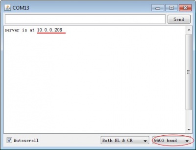
- 3.Open Serial Monitor, set the baud rate as 9600, then you can get your IP address.
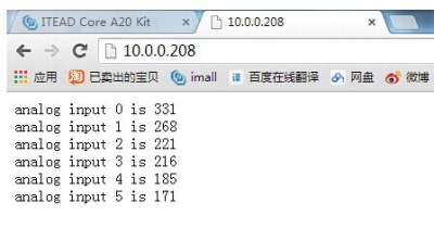
- 4.Then open your web browser, and type IP address in the address bar, you will get the analog input AD values of UNO pins from A0 to A5.
POE Test
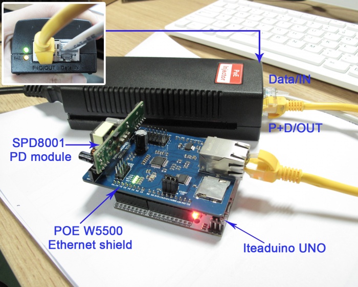
W5500 Ethernet shield supports PoE, how to make it? You need an SPD8001 to plug in the Ethernet shield. After uploading the WedServer demo in your UNO, you just unplug you the micro USB cable and do the assembly of W5500, SPD8001 PD module, PoE injector, and Iteaduino UNO as following picture.
Now, you can see all the indicators are lighting up, just type the IP address in the browser's address bar, the analog input AD values of UNO pins from A0 to A5 will be shown again. They work well in the same with powered through micro USB cable. We've tested it with Mode A/Endspan and Mode B/Midspan, they are all compatible.
Useful Link
【From Phillip Stevens】
Prepared an integrated W5500 / W5200 / W5100 code here.
- One socket.h/.c interface.
- Based on freeRTOS for AVR (Arduino).
- freeRTOS/lib_iinchip
- freeRTOS/lib_inet
What's the difference between Mode A/Endspan and Mode B/Midspan?
 Notice