Difference between revisions of "IR Shield/zh-cn"
From ITEAD Wiki
(Created page with "==Pin Map== {| class="wikitable" |- | align="center" style="background:#f0f0f0;"|'''Arduino引脚''' | align="center" style="background:#f0f0f0;"|'''描述''' |- | D0||XBEE_TX...") |
|||
| Line 50: | Line 50: | ||
{| class="wikitable" | {| class="wikitable" | ||
|- | |- | ||
| − | | align="center" style="background:#f0f0f0;"|''' | + | | align="center" style="background:#f0f0f0;"|'''Arduino引脚''' |
| − | | align="center" style="background:#f0f0f0;"|''' | + | | align="center" style="background:#f0f0f0;"|'''描述''' |
|- | |- | ||
| D0||XBEE_TX | | D0||XBEE_TX | ||
| Line 94: | Line 94: | ||
|- | |- | ||
|} | |} | ||
| − | *IR_TX: | + | *IR_TX: 当D3设置为高电平,红外发射管会向外发射信号;当D3设置为低电平,红外发射管不工作。 |
| − | *IR_RX: | + | |
| − | * | + | *IR_RX: 使用HS0038B作为IR接收模块。 |
| − | + | ||
| − | : | + | *Jumpers:跳线帽是直接连接到Arduino的IO 上,如果不需要或引脚被其他模块占用时,请移除其跳线帽。 |
| − | : | + | |
| − | : | + | :A0:上拉一个10K电阻到A0按钮上。 |
| − | * | + | |
| + | :LED1:连接到D6引脚,置高时LED1会亮。 | ||
| + | |||
| + | :LED2:连接到D7引脚,置高时LED2会亮。 | ||
| + | |||
| + | *Switch:根据Arduino主板的操作电平来设置,当主板工作在5V,开关打到5V;当主板工作在3.3V,开关打到3V3。 | ||
==Instruction== | ==Instruction== | ||
Revision as of 02:45, 9 August 2014
Contents
概述
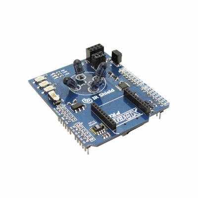
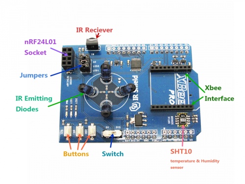
IR Shield是一块Arduino主板的扩展板,它带有红外收发模块,nRF24L01接口,XBee接口,MicroSD卡接口和温湿度传感器。有了它,你就可以监控室内的温湿度和控制红外的设备(空调,电视等等),使你的家变得更加智能化。
购买
特点
- 兼容5/3.3V主板
- micro SD卡接口
- XBee 接口
规格
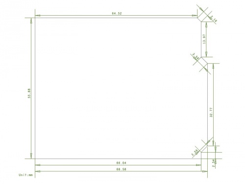
| PCB 尺寸 | 55.88mm X 68.58mm X 1.6mm |
| 电源 | 5V DC |
| 指示灯 | PWR,LED1,LED2 |
| 接口 | UART,IIC,SPI |
电气特性
| 参数 | 最小值 | 经典值 | 最大值 | 单位 |
| 电源 | 4.5 | 5 | 5.5 | VDC |
| 最高输入电压 (Target Voltage = 3.3V) | 3 | 3.3 | 3.6 | V |
| 最高输入电压 (Target Voltage = 5V) | 4.5 | 5 | 5.5 | V |
| 最低输入电压 | -0.3 | 0 | 0.5 | V |
| 电流 | - | 40 | - | mA |
硬件图
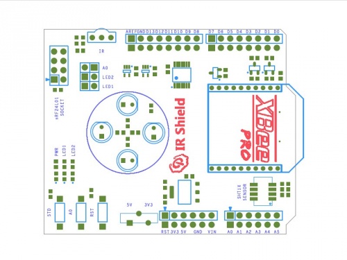
Pin Map
| Arduino引脚 | 描述 |
| D0 | XBEE_TX |
| D1 | XBEE_RX |
| D2 | nRF24L01_IRQ & STD Button |
| D3 | IR_TX* |
| D4 | SD_CS |
| D5 | IR_RX* |
| D6 | LED1* |
| D7 | LED2* |
| D8 | - |
| D9 | nRF24L01_CE |
| D10 | nRF24L01_CS |
| D11 | MOSI |
| D12 | MISO |
| D13 | SCK |
| A0 | A0 Button |
| A1 | - |
| A2 | - |
| A3 | - |
| A4 | SHT10_SDA |
| A5 | SHT10_SCL |
- IR_TX: 当D3设置为高电平,红外发射管会向外发射信号;当D3设置为低电平,红外发射管不工作。
- IR_RX: 使用HS0038B作为IR接收模块。
- Jumpers:跳线帽是直接连接到Arduino的IO 上,如果不需要或引脚被其他模块占用时,请移除其跳线帽。
- A0:上拉一个10K电阻到A0按钮上。
- LED1:连接到D6引脚,置高时LED1会亮。
- LED2:连接到D7引脚,置高时LED2会亮。
- Switch:根据Arduino主板的操作电平来设置,当主板工作在5V,开关打到5V;当主板工作在3.3V,开关打到3V3。
Instruction
Please refer to our blogs:
http://blog.iteadstudio.com/diy-intelligent-monitor-for-home-temperature-and-humidity/
Download
- Schematic--File:IM140715001-IR Shield-schematic.pdf
- IR Receiver Datasheet--File:IM140715001-HS0038B.pdf
- SHT1x Datasheet--File:SHT1x_Datasheet.pdf
- Temperature & Humidity sensor demo--File:Sht10.zip
Useful Link
http://blog.iteadstudio.com/diy-intelligent-monitor-for-home-temperature-and-humidity/
 Notice


